Centrifugal clutch and cover mount assembly therefor

a technology of centrifugal force and cover mount, which is applied in the direction of mechanical actuators, clutches, and clutches, etc., can solve the problems of insufficient centrifugal force generated to clamp the clutch plates together without substantial slipping or withou

Inactive Publication Date: 2004-12-02
DRUSSELL WILFLEY DESIGN LLC
View PDF26 Cites 14 Cited by
  • Summary
  • Abstract
  • Description
  • Claims
  • Application Information

AI Technical Summary

Benefits of technology

[0007] It is another object of the present invention to provide for a clutch housing and cover assembly which is compact, able to withstand high pressures and is easy to assemble.
[0008] It is yet another object to provide for a novel and improved cam-actuating mechanism for an automatic clutch which is capable of achieving clutch engagement at lower rpms while generating the necessary clamping force and avoiding slipping of the clutch plates in a simplified, efficient manner.
[0009] It is a further object of the present invention to provide in a centrifugal clutch, including those having internal manual override mechanisms, for an extremely compact cam mechanism which is capable of generating sufficient centrifugal force to clamp the clutch plates together without substantial slipping and within the same size case or cover as employed in stock or standard motorcycles.

Problems solved by technology

However, in certain applications it was found that there is insufficient centrifugal force generated to clamp the clutch plates together without substantial slipping or without utilizing a larger size case or cover which exceeds the space allowances within stock engine cases.

Method used


Image

  • Centrifugal clutch and cover mount assembly therefor
  • Centrifugal clutch and cover mount assembly therefor
  • Centrifugal clutch and cover mount assembly therefor

Examples


Embodiment Construction

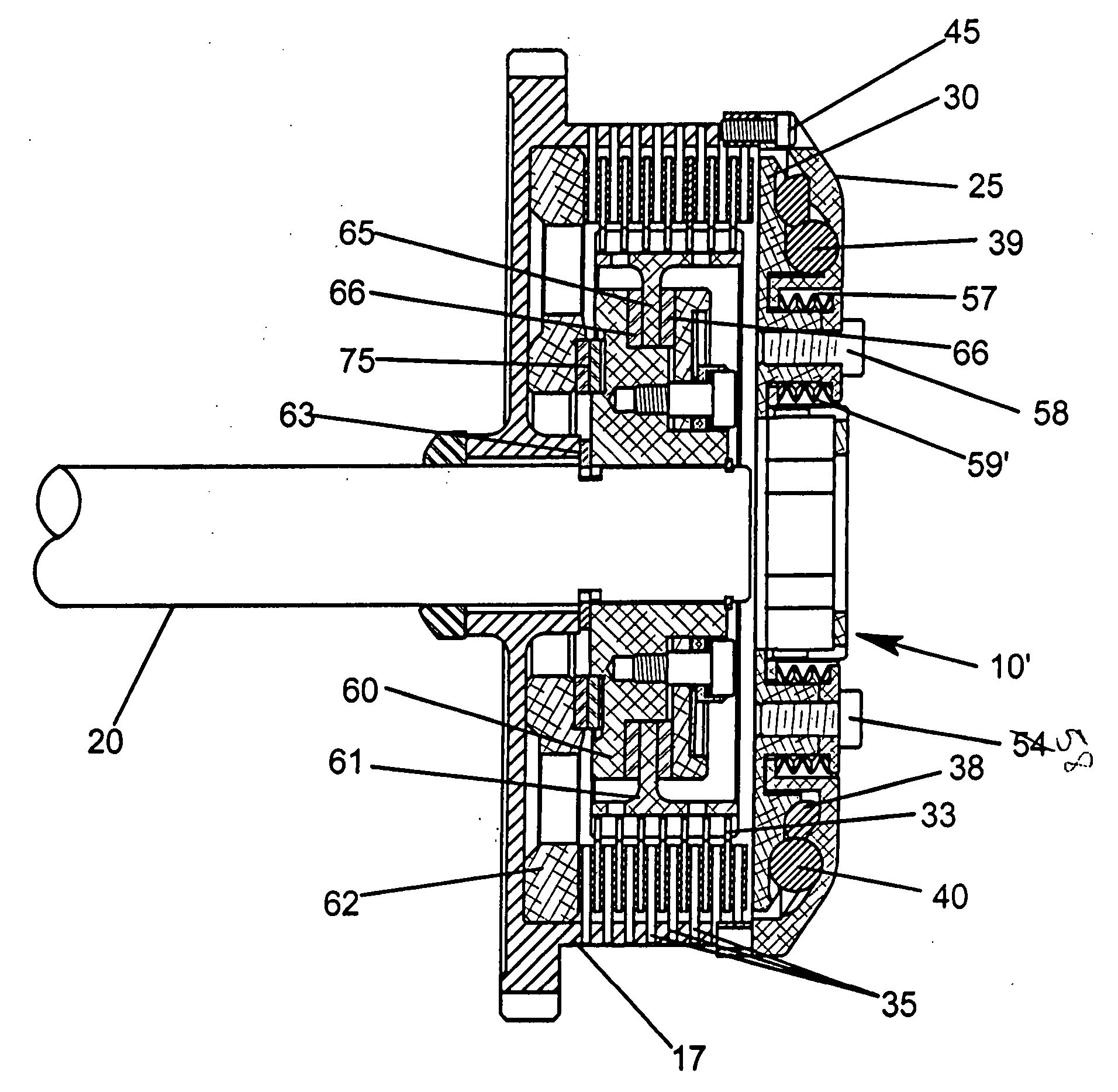
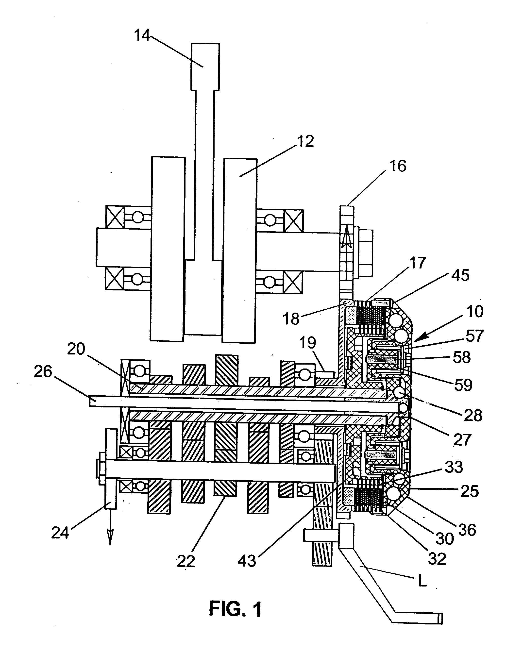
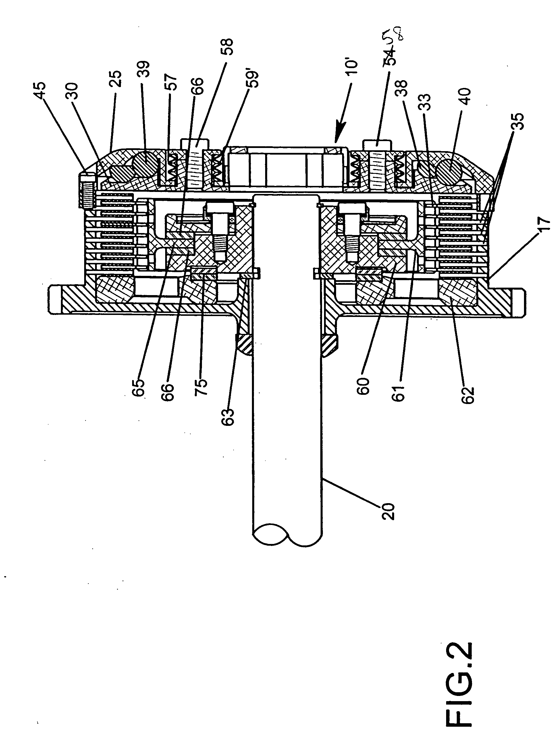
[0058] FIGS. 15 to 21 illustrate a third form of invention for a motorcycle clutch 101 and having a manual override mechanism 100 comprised of a control rod 102 with hand control lever 103, cable C and a stem 104. The stem is threadedly adjustable and locked in place by a lock nut 106, according to the length of the control rod 102, so that the receiver 104 can be axially advanced into a lockout position, as shown in FIG. 15, in response to actuation of the control lever 103. Specifically, in the lockout position, the stem 104 will act through the mounting plate 110 which is anchored by a snap ring 112 to the pressure plate 114 to prevent or lock out the clutch plates 32 from engagement with the clutch plates 33. In this respect, the pressure plate 114 is biased away from the clutch plates 32 and 33 by compression springs 136. When the clutch is accelerated up to a predetermined operating speed, a series of inner and outer rows of cam members or balls 38, 39 are urged outwardly unde...


PUM


Abstract

A clutch having a plurality of cam members between a cover and pressure plate to move outwardly under centrifugal force and cause the pressure plate to move axially to force a plurality of clutch plates into clutching engagement, a manual override mechanism to lock out the pressure plate to maintain the clutch plates in a disengaged position, and pressure limiting springs prevent shock loads from being imparted to the clutch plates when the plates are advanced into clutching engagement with one another. The clutch housing includes a cover which can be mounted either flush or inset in circumferentially spaced walls of the housing and held in place by a retaining ring inserted into slots in the side walls and is adaptable for use with any type of clutch with or without the manual override mechanism and pressure limiting springs.

Description

[0001] This application is a continuation-in-part of patent applications Ser. No. 09 / 877,518, filed Jun. 7, 2001 for AUTOMATIC CLUTCH WITH MANUAL OVERRIDE CONTROL MECHANISM by Douglas W. Drussel and George Michael Wilfley, Ser. No. 10 / 327,160, filed Dec. 20, 2002 for MULTI-ROW CAM-ACTUATED CENTRIFUGAL CLUTCH by Douglas W. Drussel and George Michael Wilfley and assigned to the assignee of this invention, and Ser. No. 10 / 791,949, filed Mar. 2, 2004 for MANUAL / AUTOMATIC PRESSURE CONTROL MECHANISM FOR CENTRIFUGAL CLUTCH, by Douglas W. Drussel and George Michael Wilfley, and assigned to the assignee of this invention, all incorporated by reference herein.BACKGROUND AND FIELD OF INVENTION[0002] This invention relates to centrifugal clutches and more particularly relates to novel and improved centrifugal clutches having high density cam members which are urged outwardly under centrifugal force in order to activate the clutching elements.[0003] Centrifugal clutches have been developed for m...

Claims


Application Information

Patent Timeline
Patent Type & Authority Applications(United States)
IPC IPC(8): F16D23/12F16D43/08F16D43/09F16D43/12
CPCF16D23/12F16D43/08F16D43/12
Inventor DRUSSEL, DOUGLAS W.WILFLEY, GEORGE MICHAEL
Owner DRUSSELL WILFLEY DESIGN LLC
Why Eureka
Try Eureka