
Spherical automatic flow emergency restrictor (S.A.F.E.R.) valve

a technology of automatic flow and restrictor, which is applied in the field of valves, can solve the problems of glass being susceptible to breakage and leakage, serious fluid leakage, and high price, and achieve the effect of enduring higher pressur

Active Publication Date: 2019-10-01
MIKRON VALVE & MFR
View PDF26 Cites 0 Cited by
  • Summary
  • Abstract
  • Description
  • Claims
  • Application Information

AI Technical Summary

Benefits of technology

The design enhances the reliability and durability of ball check valves, particularly for heavy fluids, by preventing leakage and ensuring proper seating, thus maintaining accurate fluid measurement and containment in industrial settings.

Problems solved by technology

The glass is susceptible to breakage and leakage especially in an industrial situation.
This could lead to a serious leakage of the fluid if left unchecked.
It is desired to stop the leak because the fluid may be hazardous, expensive or for cleanliness generally.
Ball check valves are susceptible to leakage, breakage and jamming after repeated use.
Ball check valves can also be unreliable in operation, particularly for certain fluids such as petroleum.
There may be a buildup on interior surfaces of the valve or a contaminant can become lodged between an interior surface and the ball.
In severe cases, the valve may become inoperative due to the ball check not seating properly, allowing fluid to flow past the ball check.

Method used


Image

  • Spherical automatic flow emergency restrictor (S.A.F.E.R.) valve
  • Spherical automatic flow emergency restrictor (S.A.F.E.R.) valve
  • Spherical automatic flow emergency restrictor (S.A.F.E.R.) valve

Examples


Embodiment Construction

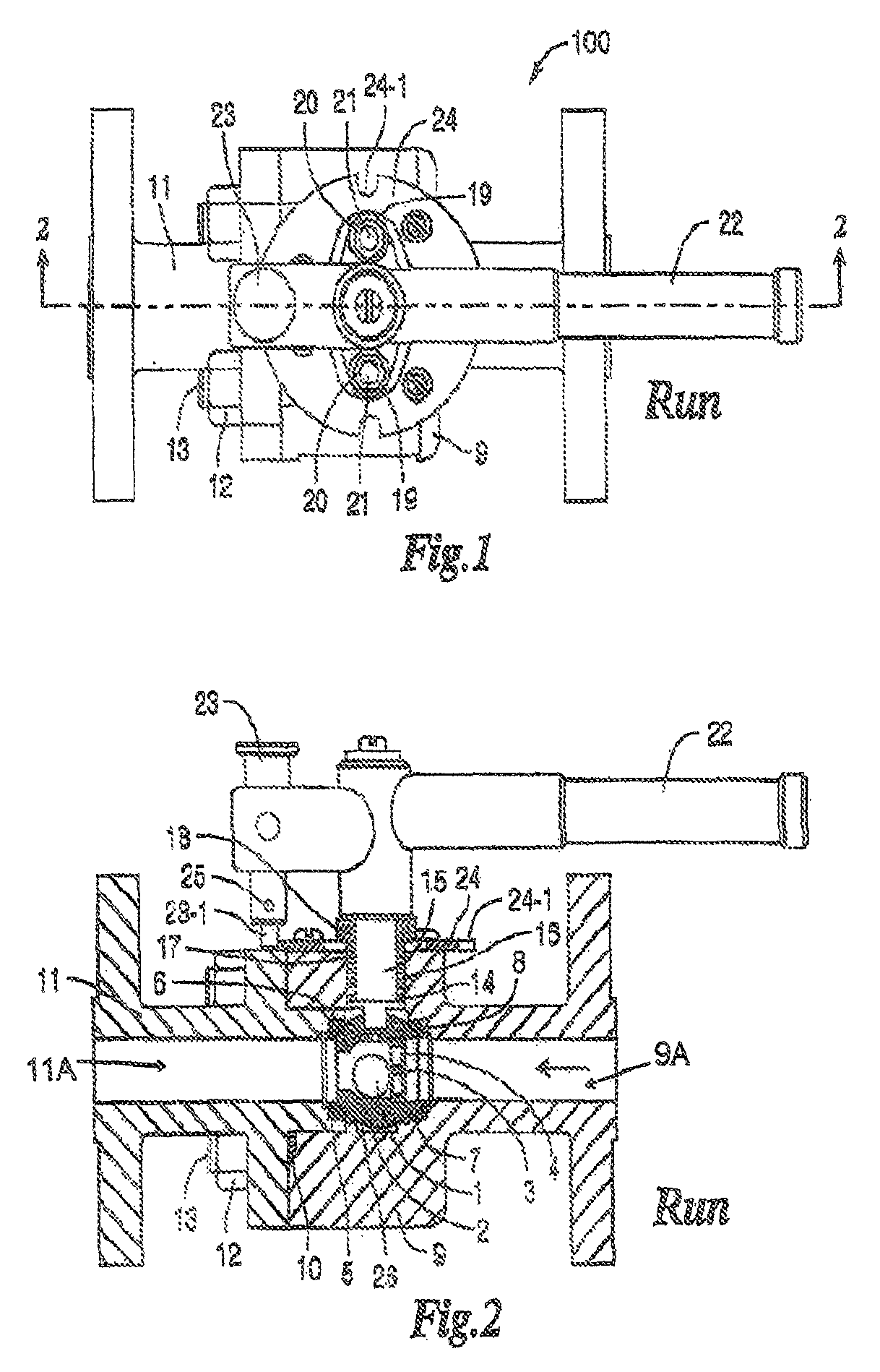
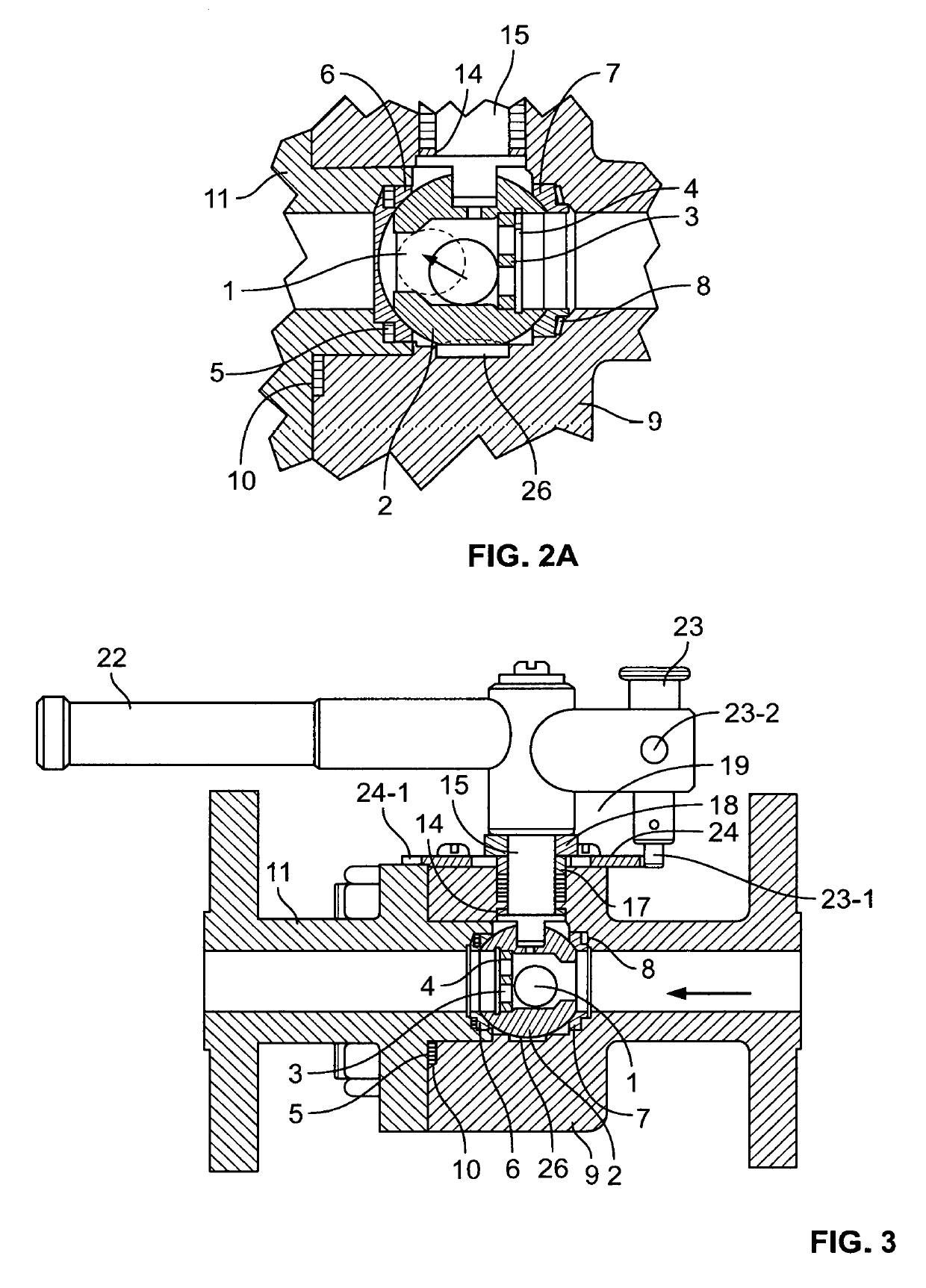
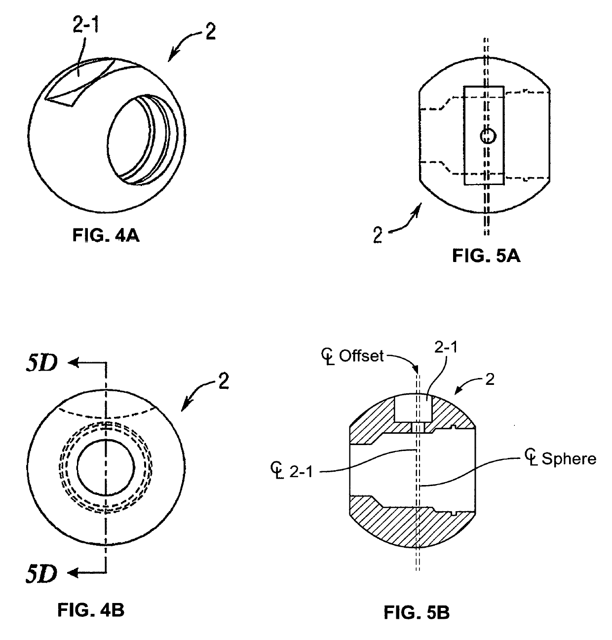
[0045]A first preferred embodiment of the invention is shown in FIGS. 1-16 with reference to the following listing of constituent parts:[0046]100 valve[0047]1 ball check[0048]2 sphere[0049]3 retainer[0050]4 retainer clip[0051]5 seat gasket[0052]6 downstream seat[0053]7 guide seat[0054]8 disc spring[0055]9 body[0056]10 body gasket[0057]11 end[0058]12 nut[0059]13 stud[0060]14 thrust washer[0061]15 stem[0062]16 stem packing[0063]17 gland ring[0064]18 gland follower[0065]19 belleville washer[0066]22 handle[0067]23 guide post[0068]24 locking plate[0069]25 stop pin

[0070]The first preferred embodiment of the valve according to the invention utilizes a body 9 and end part 11, with aligned fluid paths as shown in FIGS. 2-3. Body 9 and end 11 are of materials commensurate with the application, for example stainless steel or black oxide coated carbon steel. The valve is assembled by placing sphere 2 into a recess in body 9. The recess is formed so that the sphere 2 fluid path aligns with the f...


PUM


Abstract

A ball check valve controls the flow of fluid with a sphere. A body has a fluid path and a recess for receiving the sphere in alignment with the fluid path. The sphere has a retainer which secures a ball check within it. When the valve is in a “Run” position and the rate of fluid flow increases excessively, the ball check seats in a narrow opening of the sphere, thus restricting the flow of fluid.

Description

CROSS REFERENCE TO RELATED APPLICATIONS[0001]The present invention is filed under 35 U.S.C. § 371 as the U.S. national phase of International Application No. PCT / US2014 / 066224, filed Nov. 18, 2014, which designated the U.S. and claims priority to U.S. patent application Ser. No. 14 / 083,418, filed Nov. 18, 2013, all of which are incorporated by reference.FIELD OF THE INVENTION[0002]The invention relates generally to valves. In particular, the invention relates to ball check valves.BACKGROUND[0003]In the petroleum and some other industries, it is sometimes necessary to store large quantities of heavy fluids in a large container and keep an accurate measurement of the amount of fluid within the container. In order to accomplish this task, a sight gage is often used. The level of the fluid is measured by an upper inlet passageway and lower outlet passageway which may be connected to a cylinder which may have a glass wall or window which may be calibrated to indicate the level of the flu...

Claims


Application Information

Patent Timeline
Patent Type & Authority Patents(United States)
IPC IPC(8): F16K15/18F16K17/28F16K17/30F16K5/06F16K35/02
CPCF16K17/285F16K15/188F16K17/30F16K5/0605F16K35/025Y10T137/7841Y10T137/8803F16K15/1848
Inventor SMITH, PATRICK D.OSTAND, PAUL R.CACCAVO, JOSEPH
Owner MIKRON VALVE & MFR
Learn More