A voltage divider insulating cap for DC leakage current test of controllable arrester

A DC leakage and current test technology, which is applied in the field of arrester test, can solve the problems of small insulation distance, inability to withstand high voltage, and inability to withstand high voltage, so as to achieve the effect of increasing insulation strength and high safety

Active Publication Date: 2022-08-02
MAINTENANCE BRANCH OF STATE GRID HEBEI ELECTRIC POWER +1
View PDF13 Cites 0 Cited by
  • Summary
  • Abstract
  • Description
  • Claims
  • Application Information

AI Technical Summary

Problems solved by technology

This high voltage will be applied to both ends of the control switch at the same time, and the fracture of the switch cannot withstand high voltage
Therefore, it is necessary to remove the connecting wire between the arrester and the control switch during the test, but after removing the connecting wire, the insulation distance between the two is small and still cannot withstand high voltage

Method used


Image

  • A voltage divider insulating cap for DC leakage current test of controllable arrester
  • A voltage divider insulating cap for DC leakage current test of controllable arrester
  • A voltage divider insulating cap for DC leakage current test of controllable arrester

Examples


Embodiment 1

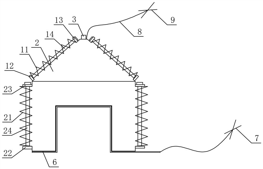
[0075] like figure 1 shown,

[0076] A voltage dividing insulating cap for a DC leakage current test of a controllable arrester, comprising a voltage dividing insulating cap body 10 and an inflatable chamber 2 located in the voltage dividing insulating cap body 10;

[0077] The bottom of the voltage dividing insulating cap body 10 is provided with a groove, and the top thereof is a tower-shaped tip.

[0078] Further, the voltage dividing insulating cap body 10 includes an insulating cap top 11 and an insulating cap side portion 21 fixedly connected below the insulating cap top 11 , and the insulating cap top 11 and the insulating cap side portion 21 are integrally formed with a silicone rubber material. made;

[0079] Further, the outer sides of the insulating cap top 11 and the insulating cap side portions 21 are both folded corrugated surfaces.

[0080] Further, the center of the top surface of the top 11 of the insulating cap is provided with SF for filling 6 Gas inflat...

Embodiment 2

[0083] like figure 1 shown,

[0084] A voltage dividing insulating cap for a DC leakage current test of a controllable arrester, comprising a voltage dividing insulating cap body 10 and an inflatable chamber 2 located in the voltage dividing insulating cap body 10;

[0085] The bottom of the voltage dividing insulating cap body 10 is provided with a groove, and the top thereof is a tower-shaped tip.

[0086] Further, the voltage dividing insulating cap body 10 includes an insulating cap top 11 and an insulating cap side portion 21 fixedly connected below the insulating cap top 11 , and the insulating cap top 11 and the insulating cap side portion 21 are integrally formed with a silicone rubber material. made;

[0087] Further, the outer sides of the insulating cap top 11 and the insulating cap side portions 21 are both folded corrugated surfaces.

[0088] Further, the center of the top surface of the top 11 of the insulating cap is provided with SF for filling 6 Gas inflat...

Embodiment 3

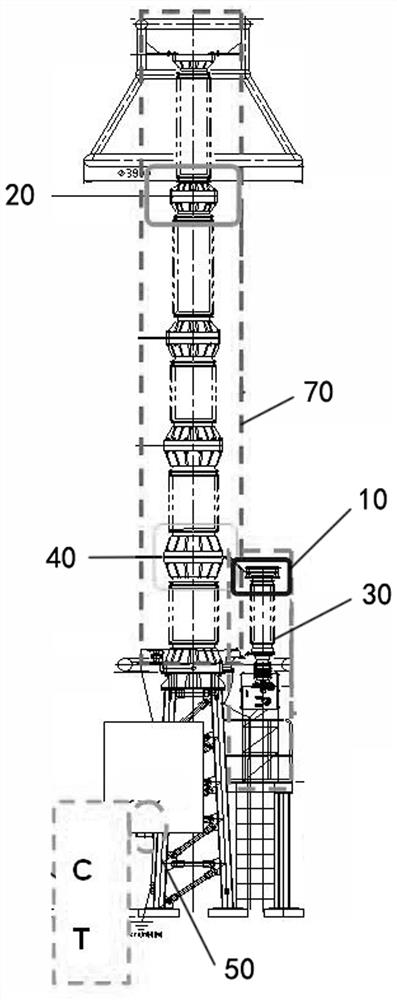
[0096] like figure 1 and 3 shown,

[0097] A voltage dividing insulating cap for a DC leakage current test of a controllable arrester, comprising a voltage dividing insulating cap body 10 and an inflatable chamber 2 located in the voltage dividing insulating cap body 10;

[0098] The bottom of the voltage dividing insulating cap body 10 is provided with a groove, and the top thereof is a tower-shaped tip.

[0099] Further, the voltage dividing insulating cap body 10 includes an insulating cap top 11 and an insulating cap side portion 21 fixedly connected below the insulating cap top 11 , and the insulating cap top 11 and the insulating cap side portion 21 are integrally formed with a silicone rubber material. made;

[0100] Further, the outer sides of the insulating cap top 11 and the insulating cap side portions 21 are both folded corrugated surfaces.

[0101] Further, the center of the top surface of the top 11 of the insulating cap is provided with SF for filling 6 Gas...


PUM


Abstract

The invention discloses a voltage dividing insulating cap for a DC leakage current test of a controllable arrester, comprising a voltage dividing insulating cap body and a gas-filled chamber located in the voltage dividing insulating cap body; the bottom of the voltage dividing insulating cap body is provided with a concave trough, the top of which is a tower-shaped tip. The voltage dividing insulating cap body includes an insulating cap top and an insulating cap side portion fixedly connected below the insulating cap top, and the insulating cap top and the insulating cap side are integrally formed with a silicone rubber material; the insulating cap top and the outer side of the insulating cap side are folded corrugated surfaces. The voltage-bearing insulating cap of the present invention can withstand voltage, and the withstand voltage value is lower than that of the existing controllable arrester in the test; SF 6 The gas insulation has high safety and is more resistant to high voltage; the voltage divider insulating cap can increase the insulation strength, adjust the insulation coordination, and realize the leakage current test of the controllable arrester without removing the controllable switch.

Description

technical field [0001] The invention relates to a voltage divider insulating cap for a DC leakage current test of a controllable arrester, and belongs to the technical field of arrester testing. Background technique [0002] The arrester is connected between the cable and the ground, usually in parallel with the protected equipment. The arrester can effectively protect the communication equipment. Once an abnormal voltage occurs, the arrester will act and play a protective role. When the communication cable or equipment is running under normal working voltage, the arrester will not work, and it is regarded as an open circuit to the ground. Once a high voltage occurs and the insulation of the protected equipment is endangered, the arrester will act immediately to guide the high-voltage surge current to the ground, thereby limiting the voltage amplitude and protecting the insulation of communication cables and equipment. When the overvoltage disappears, the arrester quickly ...

Claims


Application Information

Patent Timeline
Patent Type & Authority Patents(China)
IPC IPC(8): G01R31/52G01R1/04H01B17/56
CPCG01R31/52G01R1/0408G01R1/0425H01B17/56
Inventor 胡伟涛赵冀宁刘晓飞隋月艺付炜平冯鹏森张惠山王涛杨世博李建鹏肖方勇祝洁齐梦倩江鸿雁王红彩王雍会轩莹莹欧阳宝龙冯士桀白剑忠王绪白诗婷
Owner MAINTENANCE BRANCH OF STATE GRID HEBEI ELECTRIC POWER
Why Eureka
Try Eureka