Computer fan control circuit

A fan control and circuit technology, applied in pump control, electrical digital data processing, non-variable-capacity pumps, etc., can solve problems such as shortening the service life of computer fans, and achieve the effect of improving service life, high control accuracy and rational use

Inactive Publication Date: 2014-05-21
HONG FU JIN PRECISION IND WUHAN CO LTD +1
View PDF5 Cites 10 Cited by
  • Summary
  • Abstract
  • Description
  • Claims
  • Application Information

AI Technical Summary

Problems solved by technology

However, long-term high-speed operation will not only shorten the service life of the computer fan, but also the computer fan itself will generate a lot of heat

Method used


Image

  • Computer fan control circuit

Examples


Embodiment Construction

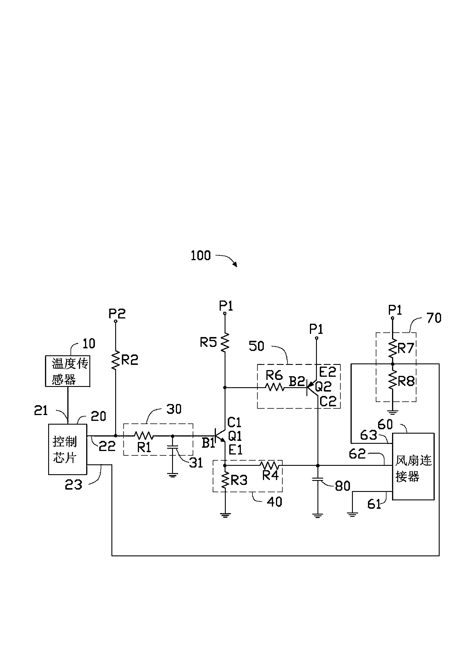
[0010] see figure 1 , which is a circuit diagram of a preferred embodiment of the computer fan control circuit of the present invention. The computer fan control circuit 100 of the present invention includes a temperature sensor 10, a control chip 20, an integrating circuit 30, a control switch Q1, a feedback circuit 40, a current control circuit 50, a fan connector 60, a signal feedback circuit 70, a first power supply P1, a first The pull-up resistor R2 , the second pull-up resistor R5 , the second power supply P2 and the filter capacitor 80 .

[0011] The temperature sensor 10 is used for sensing the temperature of the internal system of the computer.

[0012] The control chip 20 includes a temperature sensing pin 21 , a signal output pin 22 and a signal feedback pin 23 . The temperature sensing pin 21 is connected to the temperature sensor 10 for reading the temperature value of the temperature sensor 10 . The control chip 20 is used to generate a first pulse width modu...


PUM


Abstract

A computer fan control circuit which comprises a control chip, an integral circuit, a switch unit, a current control circuit, a feedback circuit and a first power source. The switch unit comprises a first end, a second end and a third end. The current control circuit comprises a current-limiting resistor and a current controller. The current controller comprises a first control end, a second control end and a third control end. The feedback circuit comprises a first feedback resistor. The control chip generates a first pulse width modulation signal. The input end of the integral circuit receives the first pulse width modulation signal. The output end of the integral circuit is connected with the first end of the switch unit. The second end of the switch unit is grounded through the first feedback circuit. The third end of the switch unit is connected with the first control end through the current-limiting resistor. The second control end is connected with the first power source. The third control end is connected with a power source pin of a fan connector. When the difference between the voltage of the first end and the voltage of the second end is smaller than a first threshold value, the switch unit is turned off, and the computer fan control circuit adjusts the rotating speed of the fan by changing the duty ratio of the first pulse width modulation signal.

Description

technical field [0001] The invention relates to a computer fan control circuit. Background technique [0002] With the rapid development of computer technology, computer systems usually have to perform a large number of calculations, and the heat generated when the task is busy is also gradually increasing. The problem of heat dissipation cannot be solved by heat dissipation holes and heat sinks alone. For active cooling devices, the cost-effective air-cooling technology has become the most commonly used cooling method for computer systems. However, in the existing air-cooling technology, the computer fan control circuit controls the speed of the computer fan to remain constant no matter when the system is busy (computer temperature is high) or when the system is running smoothly (computer temperature is low). However, long-term high-speed operation will not only shorten the service life of the computer fan, but also the computer fan itself will generate a lot of heat. Co...

Claims


Application Information

Patent Timeline
Patent Type & Authority Applications(China)
IPC IPC(8): F04D27/00
CPCG06F1/206
Inventor 陈俊生
Owner HONG FU JIN PRECISION IND WUHAN CO LTD
Why Eureka
Try Eureka