High voltage moving magnet bidirectional proportional electromagnet

A technology of proportional electromagnet and moving magnet, which is applied to electromagnets with armatures, electromagnets, circuits, etc., can solve the problems of inability to realize proportional control and inability to work, and achieve simple structure, high output force, and low manufacturing cost Effect

Inactive Publication Date: 2016-05-25
ZHEJIANG UNIVERSITY OF SCIENCE AND TECHNOLOGY
View PDF6 Cites 0 Cited by
  • Summary
  • Abstract
  • Description
  • Claims
  • Application Information

AI Technical Summary

Problems solved by technology

[0002] Proportional electromagnets can convert input electrical signals into force or displacement output, and are the core components of electro-hydraulic servo / proportional control systems, but traditional proportional electromagnets can only provide one-way drive output
Invention patent CN10155281B discloses a permanent magnet operating mechanism that uses two sets of coils to alternately energize to achieve linear reciprocating motion, but it cannot achieve proportional control and cannot work in an oil pressure environment; invention patent CN1258775C discloses a permanent magnet operating mechanism that uses permanent magnet The proportional electromagnet with two-way output can reduce the energy consumption of the system, but its moving part is a moving iron, and the magnetic saturation problem of the moving iron limits the further improvement of its output force

Method used


Image

  • High voltage moving magnet bidirectional proportional electromagnet
  • High voltage moving magnet bidirectional proportional electromagnet
  • High voltage moving magnet bidirectional proportional electromagnet

Examples


Embodiment Construction

[0018] The specific implementation manners of the present invention will be described in further detail below in conjunction with the accompanying drawings.

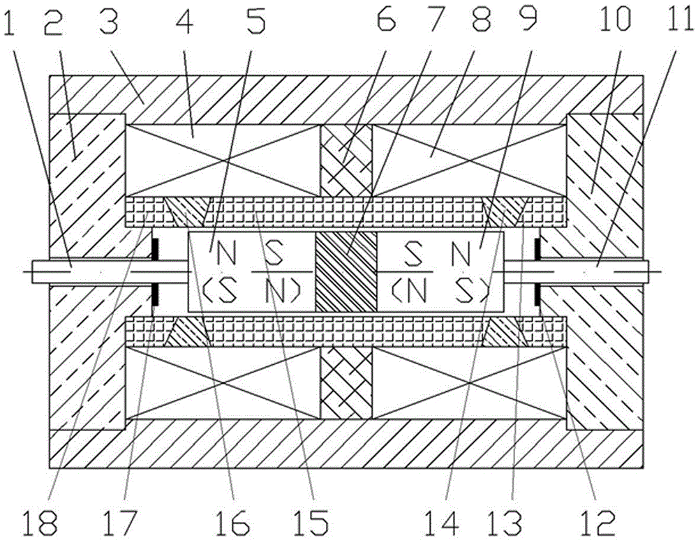
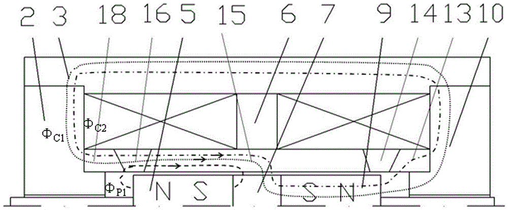
[0019] Such as Figure 1 ~ Figure 3 As shown, the high-voltage resistant moving magnet type bidirectional proportional electromagnet of the present invention includes push rods 1, 11, yoke irons 2, 10, housing 3, control coils 4, 8, first permanent magnet 5, magnetic conduction ring 6, Armature 7, the second permanent magnet 9, limit pieces 12,17, guide sleeves 13,15,18, magnetic isolation rings 14,16. The housing 3, the yokes 2, 10, the armature 7, and the guide sleeves 13, 15, 18 are all magnetizers.

[0020] The shell 3 is a hollow shell, the two ends are connected with the yokes 2, 10, the flanges of the yokes 2, 10 are matched with the inner holes of the guide sleeves 13, 15, 18, and the guide sleeves 13, 15, 18 are non-guided The magnetic isolation rings 14 and 16 made of magnetic material are separated and welde...


PUM

PropertyMeasurementUnit
thicknessaaaaaaaaaa

Abstract

The invention provides a high-pressure-resistant moving-magnet type bidirectional proportional electromagnet which comprises push rods, yokes, a shell, control coils, a first permanent magnet, a magnetic conduction ring, an armature, a second permanent magnet, limiting plates, guide sleeves and non-magnetic rings. Flanges of the yokes are matched with inner holes of the guide sleeves, and the three guide sleeves are magnetic conductors, are separated from one another by the non-magnetic rings made of non-magnetic-conduction materials and then are integrated with one another by means of welding. Compared with the prior art, the high-pressure-resistant moving-magnet type bidirectional proportional electromagnet has the advantages that the permanent magnets are used as main moving components, so that the shortcoming of constraints due to magnetic saturation and the like can be overcome, and outputted force of a system can be greatly increased; the outputted force or displacement can be bidirectionally and continuously controlled, and zero positions and dead zones can be prevented; the high-pressure-resistant moving-magnet type bidirectional proportional electromagnet is high-oil-pressure-resistant and can be used as a wet electro-mechanical converter; the high-pressure-resistant moving-magnet type bidirectional proportional electromagnet is simple in structure and low in manufacturing cost.

Description

technical field [0001] The invention relates to an electro-mechanical converter for an electro-hydraulic servo valve and a proportional valve in the field of fluid control, in particular to a high-voltage-resistant moving magnet bidirectional proportional electromagnet. Background technique [0002] Proportional electromagnets can convert input electrical signals into force or displacement output, and are the core components of electro-hydraulic servo / proportional control systems, but traditional proportional electromagnets can only provide unidirectional drive output. Invention patent CN10155281B discloses a permanent magnet operating mechanism that uses two sets of coils to alternately energize to achieve linear reciprocating motion, but it cannot achieve proportional control and cannot work in an oil pressure environment; invention patent CN1258775C discloses a permanent magnet operating mechanism that uses permanent magnet The proportional electromagnet that can be optim...

Claims


Application Information

Patent Timeline
Patent Type & Authority Patents(China)
IPC IPC(8): H01F7/08H01F7/122
Inventor 李其朋
Owner ZHEJIANG UNIVERSITY OF SCIENCE AND TECHNOLOGY
Why Eureka
Try Eureka