

Brake structure of traction machine
a technology of traction machine and brake, which is applied in the direction of braking system, braking equipment, transportation and packaging, etc., can solve the problems of increasing manufacturing cost, on/off action of brake, and eventual breakage of connecting members
- Summary
- Abstract
- Description
- Claims
- Application Information
AI Technical Summary
Benefits of technology
Problems solved by technology
Method used
Image

Examples
first embodiment
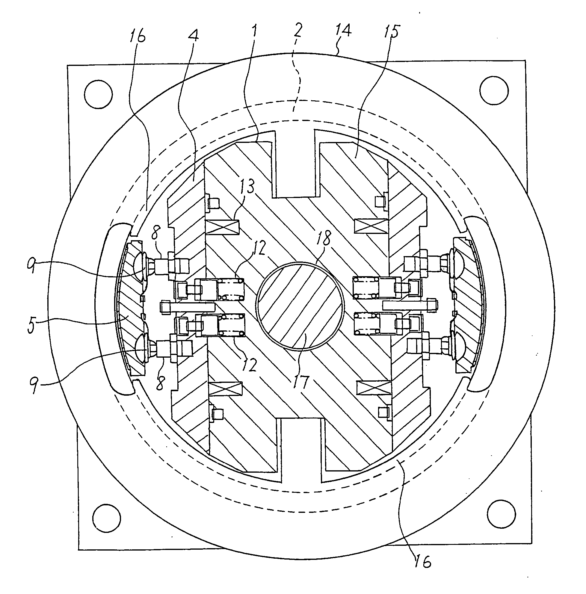
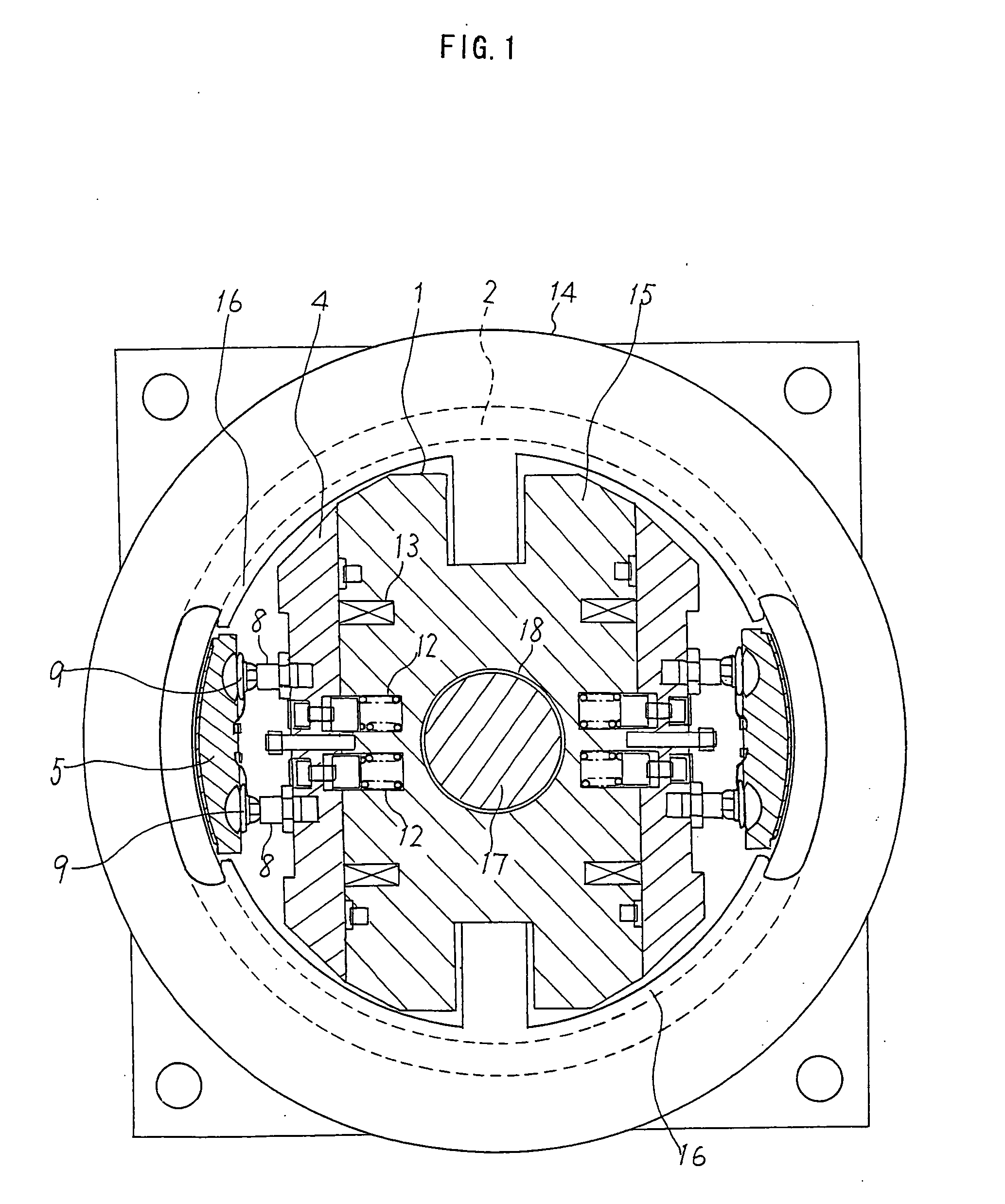
[0026] FIG. 1 is a plan view showing a structure of a brake of a traction machine according to the invention.
[0027] Referring to FIG. 1, the brake structure includes a cylindrical brake drum 2 which is fixedly attached to a rotating body of the traction machine and made rotatable about a central axis of a shaft 17 extending from a later-described housing 14 as well as an electromagnetic brake unit 1 disposed in an inner space of the brake drum 2. The electromagnetic brake unit 1 fixed in a nonrotatable manner includes a pair of movable iron cores 4 and a one-piece formed stationary iron core block 15. The stationary iron core block 15 has a pair of stationary iron core portions facing the individual movable iron cores 4.
[0028] The brake drum 2 is mounted on the shaft 17 with a bearing placed in between so that the brake drum 2 can rotate about the shaft 17.
[0029] There is formed a hole 18 at the center of the one-piece formed stationary iron core block 15 and the shaft 17 is firmly ...
second embodiment
[0044] While the one-piece formed stationary iron core block 15 is fixed to the housing 14 by fixing the shaft 17 in the hole 18 formed in the stationary iron core block 15 by shrink fit or expansion fit, the stationary iron core block 15 may be fixed to the housing 14 by bolt joints.
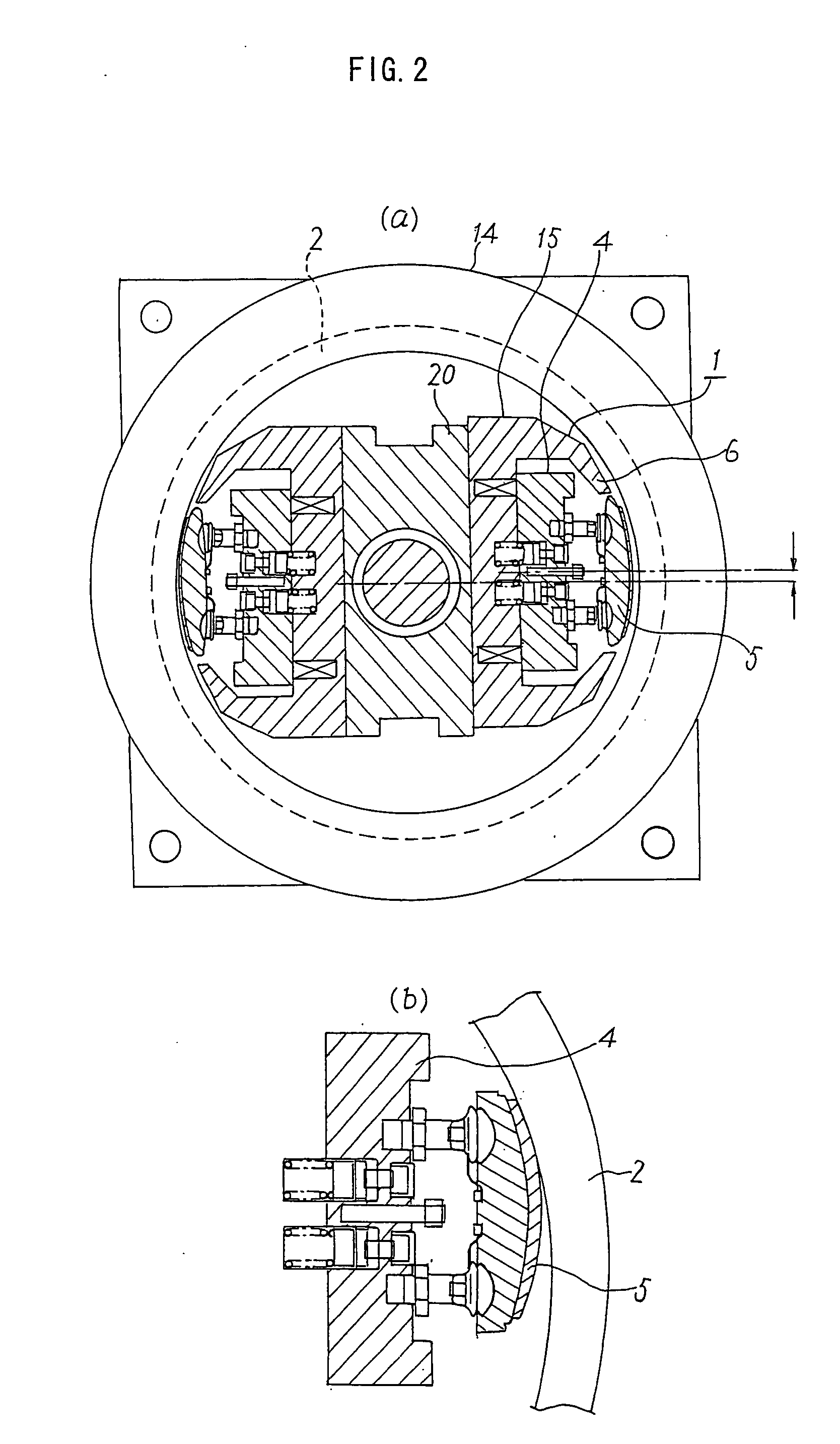
[0045] FIG. 3A is a fragmentary sectional side view showing a structure of a brake adapted to a traction machine according to a second embodiment of the invention, and FIG. 3B is an enlarged fragmentary sectional side view of the brake structure of the second embodiment, in which elements identical or similar to those of the first embodiment are designated by the same reference numerals.
[0046] In this embodiment, there is formed a flange 19 at a basal part of the shaft 17 extending from the housing 14, the flange 19 having a surface perpendicular to the central axis of the shaft 17. The one-piece formed stationary iron core block 15 is placed against the surface perpendicular to the central axis of the ...
third embodiment
[0049] FIG. 4 is a plan view showing a structure of a brake of a traction machine according to a third embodiment of the invention, in which elements identical or similar to those of the foregoing embodiments are designated by the same reference numerals.
[0050] While each brake shoe 5 is connected to the corresponding movable iron core 4 by a pair of shoe supports 9 in the brake structure of the first embodiment, each brake shoe 5 is supported by a single shoe support 9 joined to the movable iron core 4 by a single connecting member 8 in the brake structure of the third embodiment illustrated in FIG. 4.
[0051] As each brake shoe 5 is supported by one each shoe support 9 and connecting member 8, the brake shoes 5 can easily rotate, or swivel, in circumferential directions along the curved inner surface of the brake drum 2 and in a plane containing the central axis of the shaft 17. Even when a disturbance occurs to normal functioning of the brake, such as biting of dust or dirt between...
PUM
 Abstract
Description
Claims
Application Information