Baffle filter

a filter and baffle technology, applied in the field of improved baffle filters, can solve the problems of inconvenient installation, use, cleaning, and storage of conventional cartridge filters, and the average amount of pollutants removed from the exhaust air of the baffle filter, and achieve the effect of small physical profil

Inactive Publication Date: 2005-01-06
CADDY CORP OF AMERICA
View PDF2 Cites 32 Cited by
  • Summary
  • Abstract
  • Description
  • Claims
  • Application Information

AI Technical Summary

Benefits of technology

[0013] An object of the present invention is to provide an exhaust baffle filter that combines the benefits of conventional cartridge filters while maintaining the smaller physical profile of conventional baffle filters.

Problems solved by technology

First, because the depth of a conventional filter is approximately 2 inches, the baffle filter provides a relatively small fire barrier.
Second, because linear air flow distance is only 3 to 4 inches, coupled with the low intake velocity, only an average amount of pollutants are removed from the exhaust air.
This also causes pollutants to adhere to the various surfaces, thus separating the pollutants from the exhaust air.
However, the large and bulky size makes the conventional cartridge filter inconvenient to install, use, clean, and store.

Method used


Image

  • Baffle filter
  • Baffle filter
  • Baffle filter

Examples


Embodiment Construction

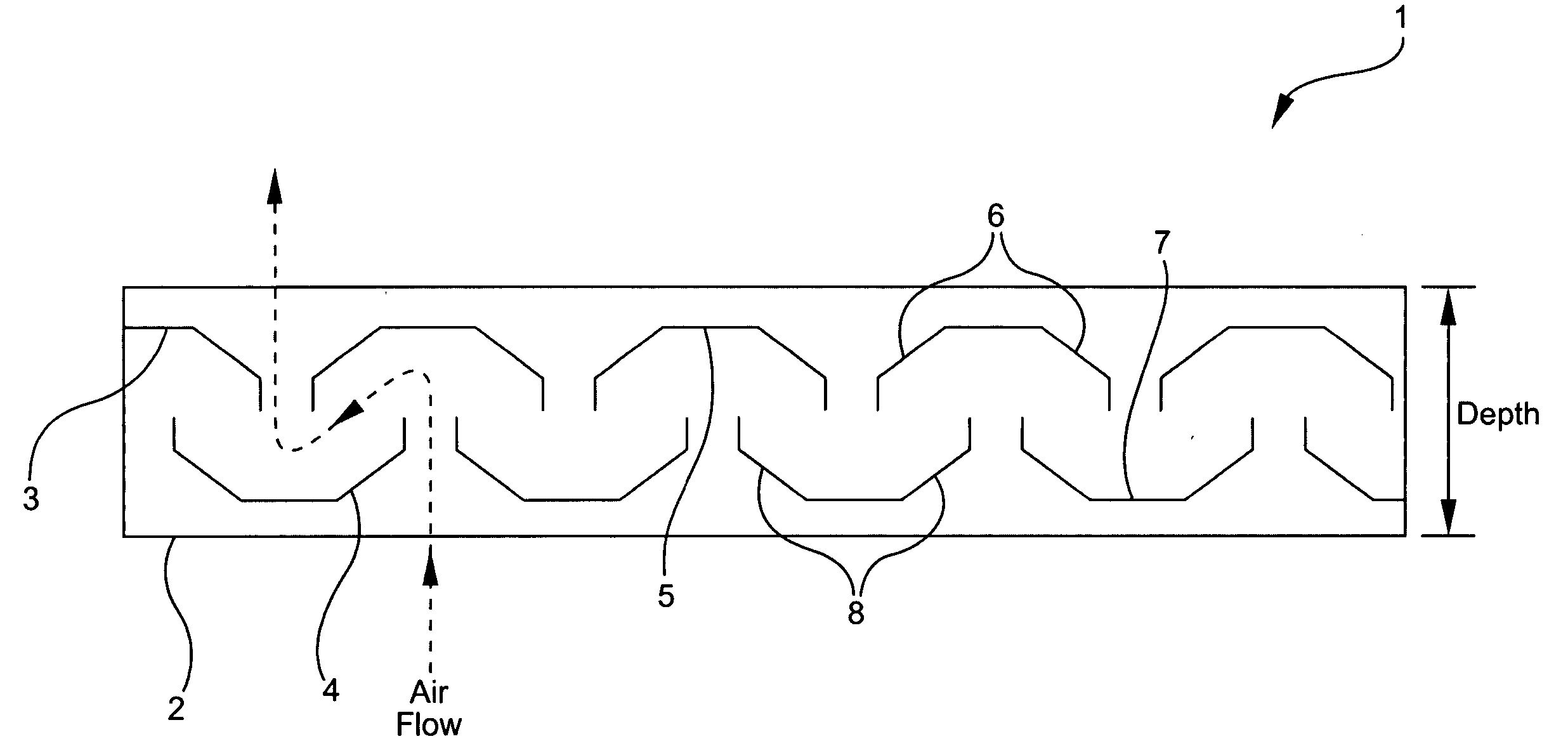
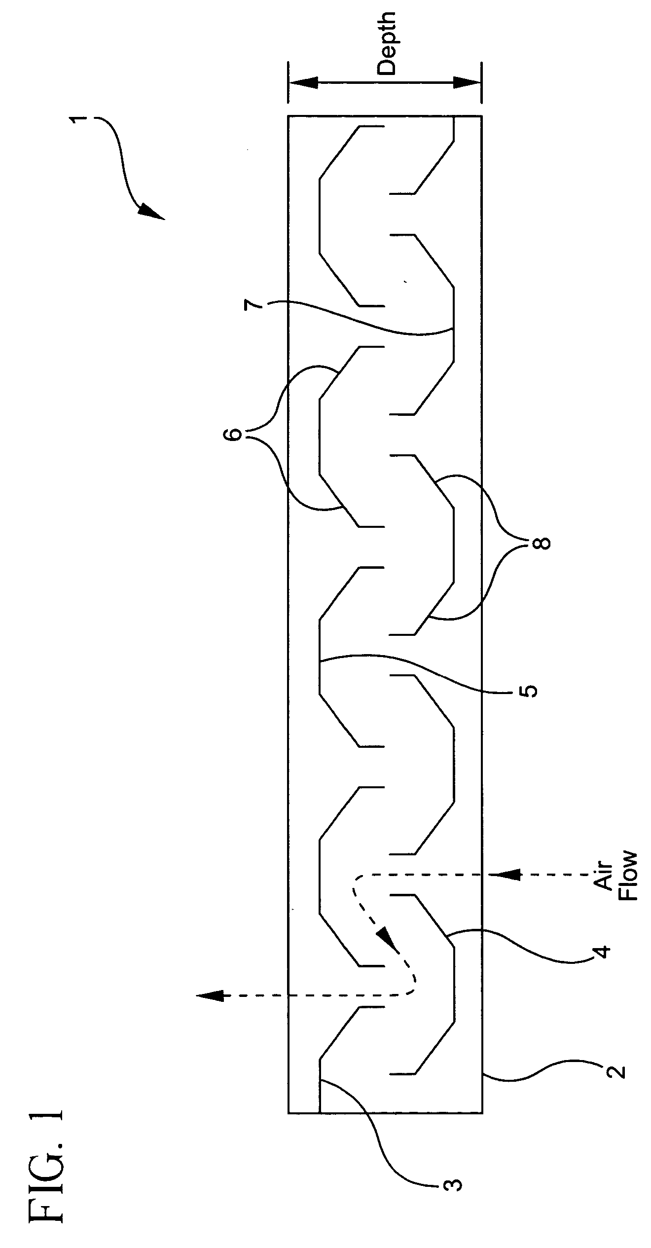
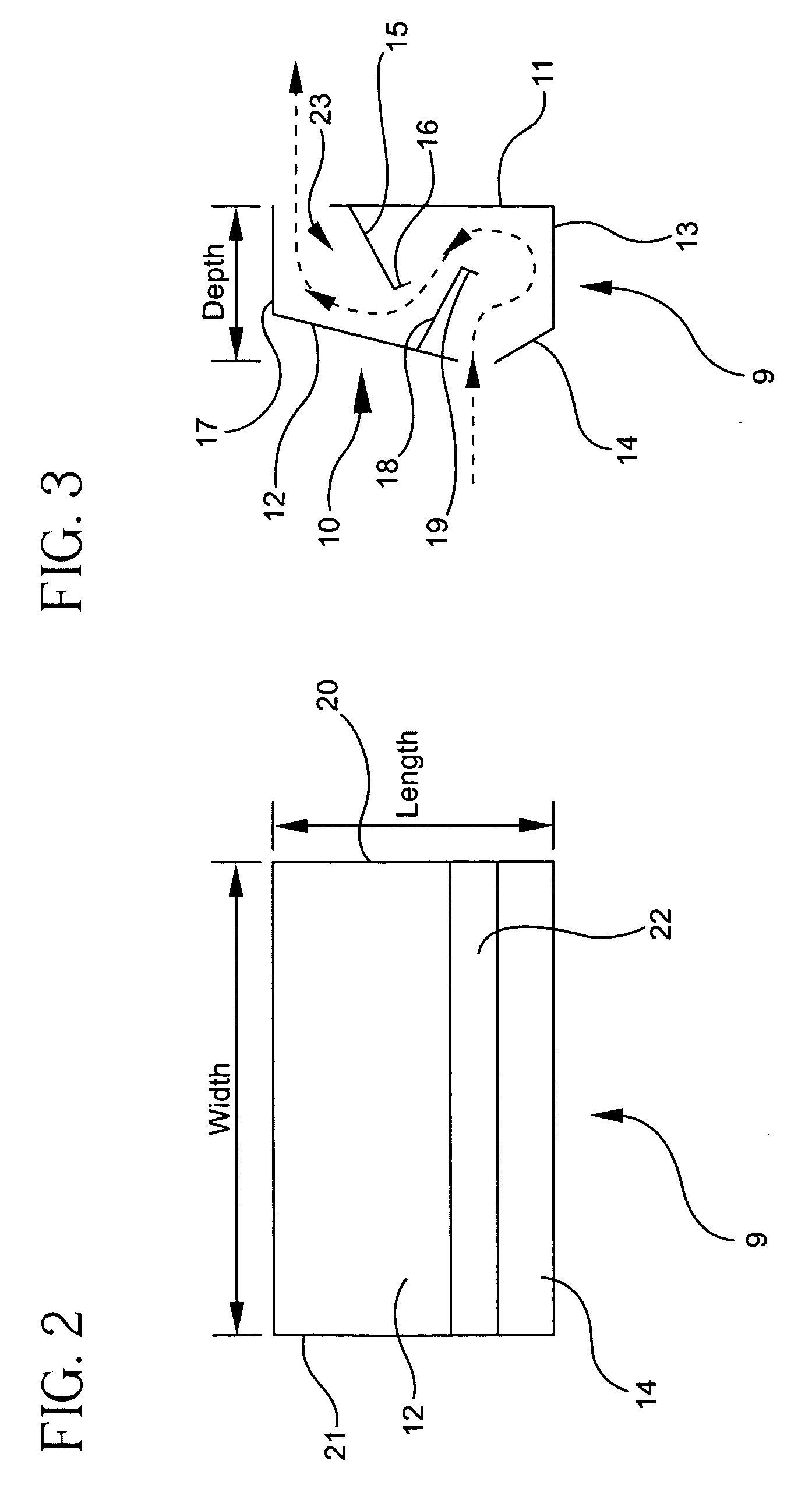
[0027]FIG. 4 is a sectional view of a filter 24 according to an embodiment of the invention. The filter 24 includes, as configured in FIG. 4, a baffle filter 25 consisting of more than one baffle channels 28, one or more inlet plates 26 that restricts the amount of exhaust air intake into the baffle filter 25 by reducing the intake area, and one or more outlet plates 27 that restricts the amount of exhaust air out take by reducing the outlet area of the baffle filter 25.

[0028] The inlet outlet plates may be composed of fire resistant material, such as galvanized or stainless steel, and / or equivalent materials that are well known in the art, such as plate materials (copper, brass, cold rolled steal, etc.) and / or heat resistant composites. The plates have a width that is approximately equal to the width of the baffle filter. The length of the plates is less than the total length of the baffle. The length of the inlet plate 26 does not have to be equal to the length of the outlet plat...


PUM

PropertyMeasurementUnit
depthaaaaaaaaaa
widthaaaaaaaaaa
lengthaaaaaaaaaa

Abstract

An apparatus is provided for filtering pollutants from exhaust air. The apparatus includes a baffle filter, at least one inlet flow plate, and at least one outlet flow plate. The baffle filter has an inlet-side and an outlet-side, and includes a plurality of baffle channels. The at least one inlet flow plate attaches to the inlet-side of the baffle filter and covers a portion of the plurality of baffle channels. The at least one outlet flow plate attaches to the outlet-side of the baffle filter and covers another portion of the plurality of baffle channels.

Description

[0001] This application claims the benefit of U.S. Provisional Application No. 60 / 473,149, filed May 27, 2003, the disclosure of which is hereby incorporated by reference in its entirety, as if fully set forth herein.BACKGROUND OF THE INVENTION [0002] 1. Field of the Invention [0003] The present invention relates to an improved baffle filter for filtering grease, fat, and other pollutants from exhaust air. [0004] 2. Description of the Related Art [0005] A hood with an exhaust fan is positioned above most kitchen cooking elements (stoves, ranges, ovens, etc.) for venting smoke, steam, grease, fat, and the like away from the cooking area. To trap the grease, fat, and other pollutants (hereinafter generally referred to as “pollutants”) before reaching the exhaust fan, a filter is positioned between the hood opening and the exhaust fan. Typical commercial-grade filters include baffle filters and cartridge filters. [0006]FIG. 1 depicts a cross-sectional view of a conventional baffle filt...

Claims


Application Information

Patent Timeline
Patent Type & Authority Applications(United States)
IPC IPC(8): B01D45/08F24C15/20
CPCF24C15/2035B01D45/08
Inventor CARTER, THOMAS ERIC
Owner CADDY CORP OF AMERICA
Why Eureka
Try Eureka