Pulsed combustion engine

a combustion engine and pulse technology, applied in the field of engines, can solve the problems of notoriously inefficient combustion of conventional gas turbine engines

Inactive Publication Date: 2005-01-06
UNITED TECH CORP
View PDF37 Cites 16 Cited by
  • Summary
  • Abstract
  • Description
  • Claims
  • Application Information

AI Technical Summary

Benefits of technology

[0008] In various implementations, there may be a first airflow substantially through the compressor and turbine and a first portion of the first airflow may pass through the combustion chamber conduits in the charges and a second portion of the first airflow may bypass combustion. A mass flow ratio of the first portion to the second portion may be between 1:1 and 1:3. The engine may be a turbofan and the first airflow may be a core airflow. A bypass airflow may bypass the compressor and turbine. A mass flow ratio of the bypass airflow to the core airflow may be between 3:1 and 9:1. The combustion may comprise detonation. The turbine and compressor may each comprise high and low stages on respective high and low spools. The array may be on a free spool and its rotation may be driven by partially tangential direction of the products of combustion. The conduits may be at least partially tangentially directed. The conduits may be substantially longitudinally directed and the engine may in

Problems solved by technology

Such conventional gas turbine engine combustion is notoriously

Method used


Image

  • Pulsed combustion engine
  • Pulsed combustion engine
  • Pulsed combustion engine

Examples


Embodiment Construction

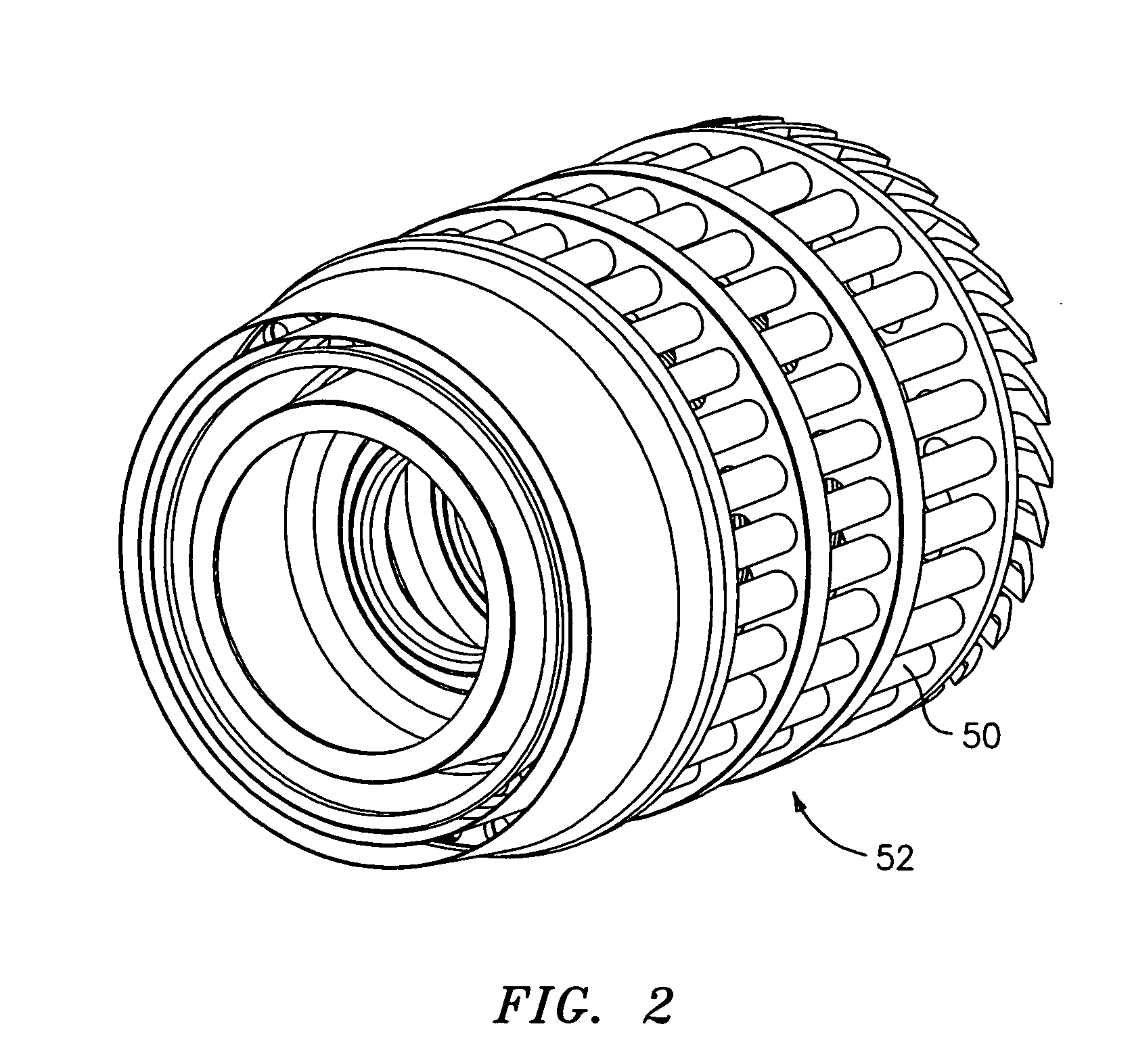
[0025] In lieu of conventional Rankine cycle combustion, a number of pulse combustion devices may be located in one or more rings about the engine. The rings are located on a rotating carousel, rotation of which passes each device through a first portion of a rotation during which the device is charged and to a second portion in which it is discharged, with combustion occurring between. In a given 360° of rotation there may be more than one pair of charging and discharging phases. The rotation may be driven by one of the turbine's spools or by tangential diversion of gases discharged by the devices.

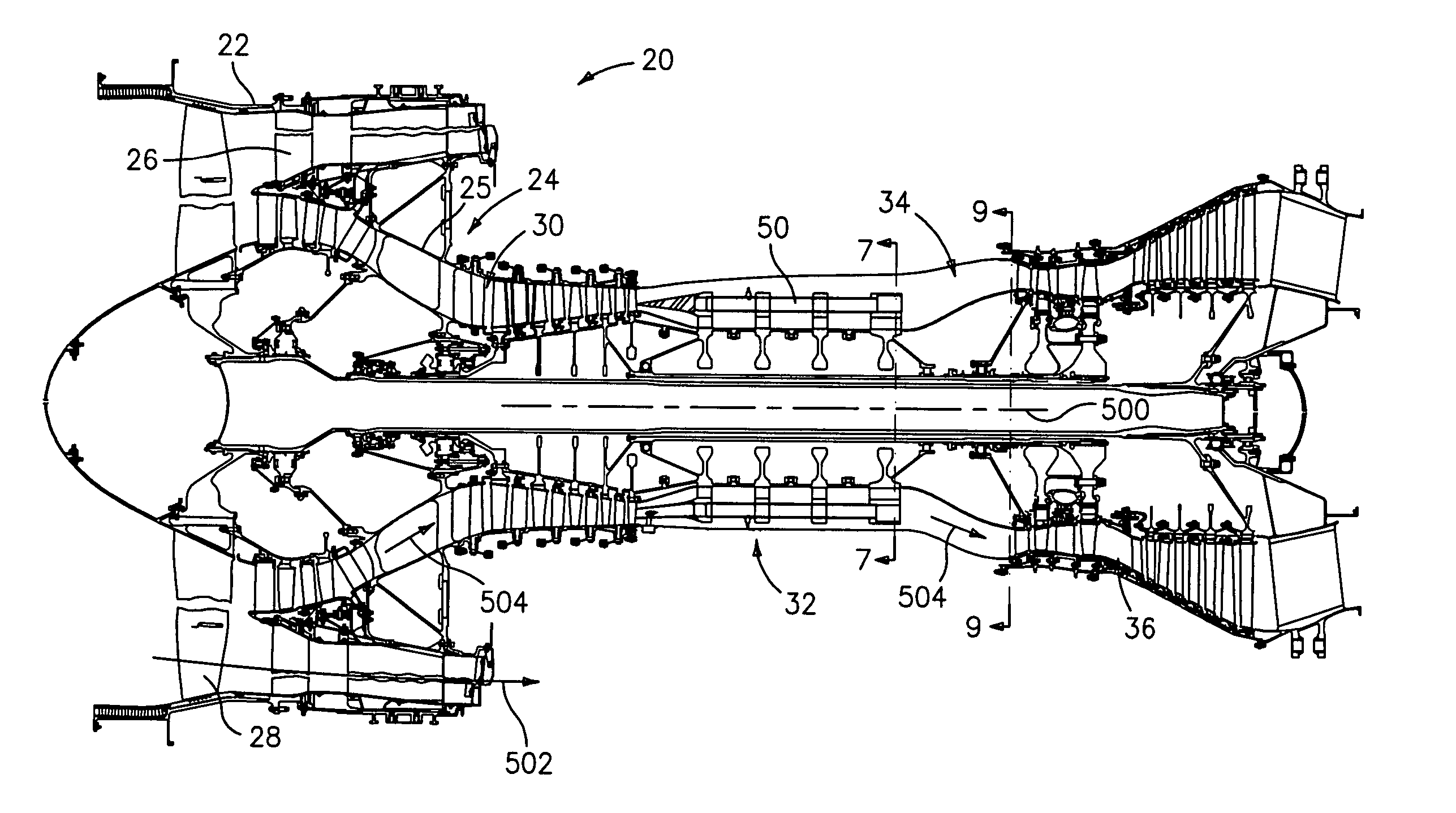
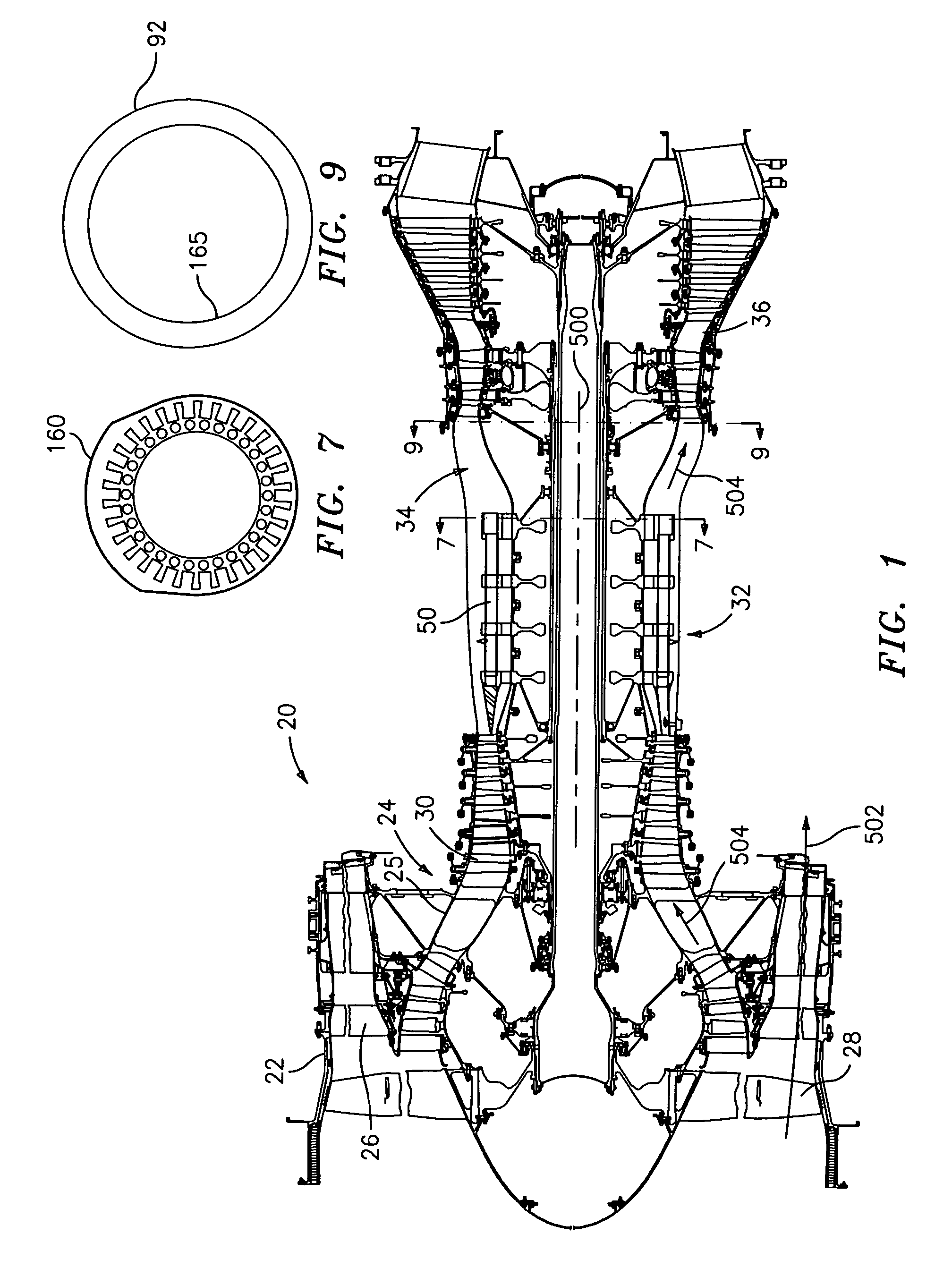
[0026]FIG. 1 shows a turbofan engine 20 having central longitudinal axis 500, a duct 22 and a core 24. The duct is supported relative to a case assembly 25 of the core by vanes 26. Of inlet air entering the duct, a fan 28 drives a bypass portion along a first flow path 502 radially between the duct and the core and core portion along a second flowpath 504 through the core. In the core do...


PUM


Abstract

A pulsed combustion device includes a support structure and a combustor carousel supported by the support structure and rotating relative thereto about an axis. The carousel has a number of combustion conduits in a circumferential array. Each conduit cyclically receives a charge and discharges combustion products of the charge.

Description

[0001] This is a Continuation-in-Part of Ser. No. 10 / 334,019, filed Dec. 30, 2002, and entitled “COMBUSTION IGNITION”. Ser. No. 10 / 334,019 is incorporated herein by reference as if set forth at length.BACKGROUND OF THE INVENTION [0002] (1) Field of the Invention [0003] This invention relates to engines, and more particularly to hybrid pulse combustion turbine engines. [0004] (2) Description of the Related Art [0005] In a conventional gas turbine engine, combustion occurs in a continuous, near constant pressure (Rankine cycle), mode. Such conventional gas turbine engine combustion is notoriously inefficient and has led to many efforts to improve efficiency. [0006] It has been proposed to apply the more efficient combustion of near constant volume combustion pulse detonation engines (PDEs) to turbine engine combustors. In a generalized PDE, fuel and oxidizer (e.g., oxygen-containing gas such as air) are admitted to an elongate combustion chamber at an upstream inlet end, typically thr...

Claims


Application Information

Patent Timeline
IPC IPC(8): F02C3/16F02C5/02F02C5/04F02C5/11F02K3/06F02K7/02F02K7/075
CPCF02C3/16F02C3/165F02C5/02F02K7/075F02C5/11F02K3/06F02K7/02F02C5/04
Inventor SAMMANN, BRADLEY C.TWELVES,, WENDELL V. JR.JONES, GARY D.NORRIS, JAMES W.KLEIN, HARVEY L.JONES, JAMES E.KRAMER, STEPHEN K.THONEBE, DOUGLAS A.
Owner UNITED TECH CORP
Why Eureka
Try Eureka