Cutter with laser generator that irradiates cutting position on workpiece to facilitate alignment of blade with cutting position

a laser generator and cutter technology, applied in the field of cutters, can solve the problems of only being able to irradiate the workpiece, undesirable overall enlargement of the cutter, etc., and achieve the effect of eliminating looseness and easy adjustmen

Inactive Publication Date: 2005-01-06
HITACHI KOKI CO LTD
View PDF27 Cites 15 Cited by
  • Summary
  • Abstract
  • Description
  • Claims
  • Application Information

AI Technical Summary

Benefits of technology

[0023] A cutter according to another aspect of the present invention includes a base, a cutter blade portion, a laser generator, a laser generator support member, and means for moving the light emitting portion of the laser generator in a horizontal direction. The laser generator support member supports therein the laser generator slidable in the horizontal direction. The moving means is adapted for moving the light emitting portion of the laser generator in the horizontal direction. With this configuration, the position of the light emitting portion can be easily adjusted in the horizontal direction using a simple moving means such as a screw.
[0024] A cutter according to still another aspect of the present invention includes a base, a cutter blade portion, a laser generator, a laser generator support member, a pivot means, first and second regulation members screwingly fitted in the laser generator support member, and first and second resilient means. The pivot means enables the laser generator to pivot horizontally and vertically in the laser generator support member. The first regulation member presses against the laser generator to pivot the laser generator horizontally about the pivot means, and the second regulation member presses against the laser generator to pivot the laser generator vertically about the pivot means. The first and second resilient means urge the laser generator toward the first and second regulation members, respectively. This configuration enables easy adjustment of the laser generator in both vertical and horizontal directions, while eliminating any looseness of fit between the laser generator and the laser generator support member.

Problems solved by technology

As a result, the user is only capable of irradiating the workpiece with the laser light in alignment with the exterior of the right or left edge of the cutting width W2.
This extension member makes gets in the way during cutting operations, and contributes to undesirable overall enlargement of the cutter.

Method used


Image

  • Cutter with laser generator that irradiates cutting position on workpiece to facilitate alignment of blade with cutting position
  • Cutter with laser generator that irradiates cutting position on workpiece to facilitate alignment of blade with cutting position
  • Cutter with laser generator that irradiates cutting position on workpiece to facilitate alignment of blade with cutting position

Examples


first embodiment

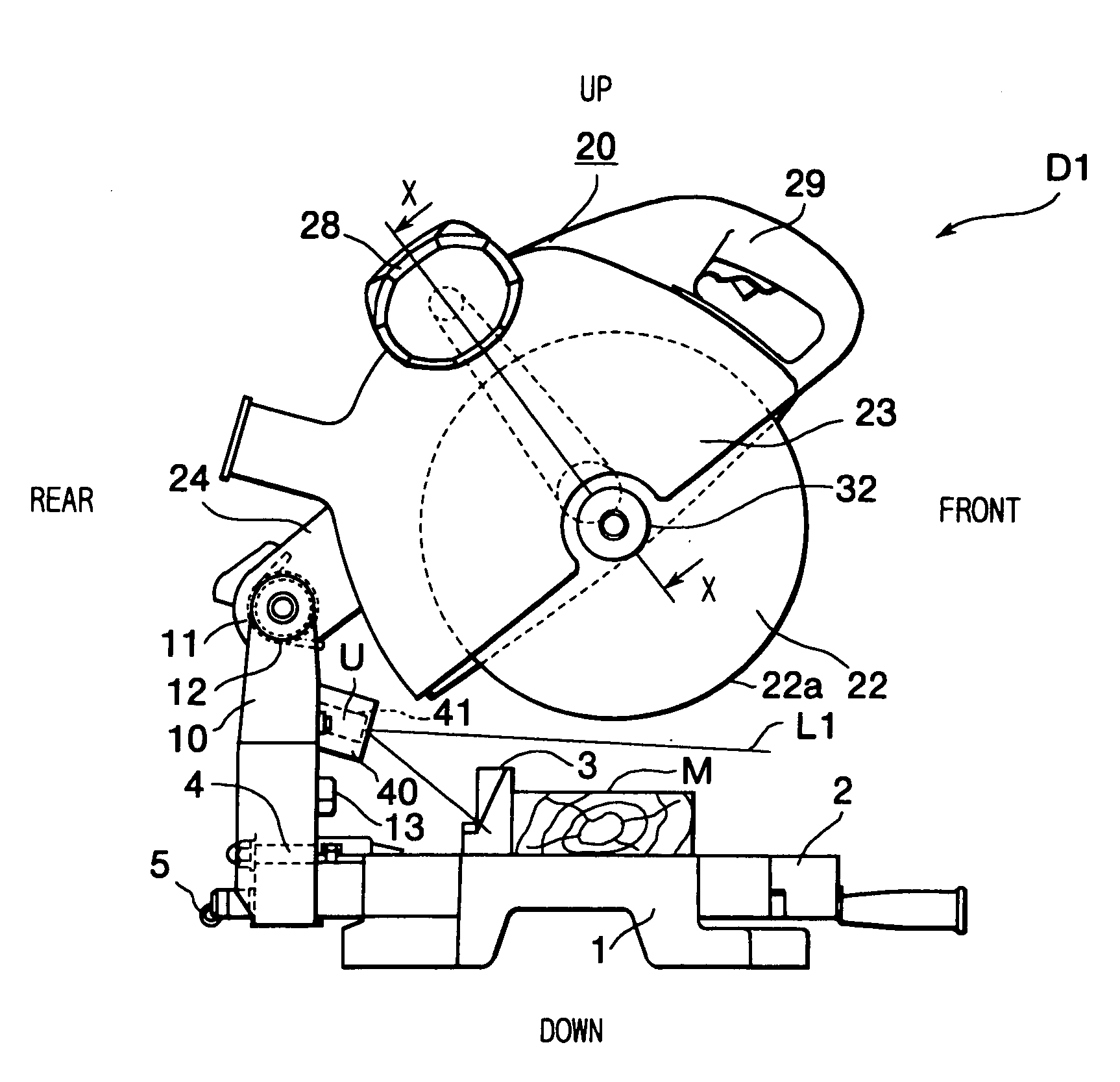
[0081] First, a cutter D1 will be described while referring to FIGS. 8 to 14. As shown in FIG. 8, the cutter D1 has a base 1, a turntable 2, a fence 3, a holder shaft 4, a holder 10, a clamp lever 5, a shaft 11, a cutter mechanism 20, and a laser unit U. The turntable 2 is supported on the center of the base 1 so as to be freely rotatable horizontally. The upper surface of the turntable 2 shares the same plane with the upper surface of the base 1. A workpiece M, such as a wooden board, is placed on the upper surfaces of the base 1 and the turntable 2. The fence 3 is fixed on the upper surface of the base 1 to support the side surface of the workpiece M. The holder 10 is supported in an upright posture on the rear end of the turntable 2 by the holder shaft 4. The axial center of the holder shaft 4 is aligned substantially with the upper surface of the turntable 2. The holder 10 can be pivoted leftward or rightward with respect to the surface of the turntable 2 about the holder shaft...

eighth embodiment

[0122] As shown in FIGS. 33 to 35, an angular indentation 40h is formed in the inner surface of the left wall of the support member 840, near the front of the support member 840. An angular protrusion 41f is formed at the left side of the laser generator 841, at a position corresponding to the position of the angular indentation 40h. Other configuration is the same as described for the

[0123] With the configurations of the eighth and ninth embodiments, the position where the laser light L1 falls incident on the workpiece M can be adjusted in precise alignment with vertical and horizontal reference lines X, Y in a manner similar to that described in the seventh embodiment, so that the laser light L1 can be properly and easily positioned into alignment with a desired cutting position.

[0124] Next, the tenth embodiment of the present invention will be described while referring FIGS. 36 to 39. The cutter according to the tenth embodiment has substantially the,same configuration as the cu...


PUM

PropertyMeasurementUnit
width W2aaaaaaaaaa
outer diameteraaaaaaaaaa
width W1aaaaaaaaaa

Abstract

A cutter including a base, a holder, a cutter blade portion, and a laser generator. The holder is supported on the base portion in an upright posture. The cutter blade portion supports a moving blade. The cutter blade portion is supported on the holder movable between an upper position and a lower position. The cutter blade portion is moved into the lower position to cut a workpiece supported on the base using the moving blade. The laser generator is attached to the holder or the cutter blade portion in an orientation to direct at least a portion of the laser light onto a position on the workpiece that is directly beneath the cutter blade portion when the cutter blade portion is in the upper position. Alternatively, a holder has a shaft support portion, and a slide shaft is axially slidably supported by the shaft support portion. A front end of the slide shaft has a hinge holder which pivotally supports the cutting blade portion. A laser generator is fixed to a front side of the hinge holder.

Description

CROSS REFERENCE TO RELATED APPLICATION [0001] This application is a continuation-in-part of copending U.S. patent application Ser. No. 09 / 499,385 filed Feb. 7, 2000, and further claims priority based on 35 U.S.C. section 119 to Japanese Patent Application Nos. 11-28275 filed Feb. 5, 1999, 11-28277 filed Feb. 5, 1999, 11-335411 filed Nov. 26, 1999, and 11-344301 filed Dec. 3, 1999.BACKGROUND OF THE INVENTION [0002] 1. Field of the Invention [0003] The present invention relates to a cutter, such as a tabletop circular saw for cutting wooden boards. [0004] 2. Description of the Related Art [0005] There has been known a cutter with a circular blade and a laser generator. The laser generator irradiates the workpiece with a laser light to indicate the position where the cutting is to be performed. The operator then uses the circular blade to cut the workpiece material at the position indicated by the laser light. [0006] Japanese Utility-Model-Application Publication No. SHO-62-150019 disc...

Claims


Application Information

Patent Timeline
Patent Type & Authority Applications(United States)
IPC IPC(8): B23D59/00B26D7/01
CPCB23D59/003B26D7/01Y10T83/762Y10T83/7697Y10T83/7705Y10T83/7726Y10T83/7788Y10T83/828Y10T83/839Y10T83/853Y10T83/858Y10T83/8773
Inventor USHIWATA, SHIGEHARUTAKANO, SHINJITERASHIMA, HIDEAKIMATSUNAGA, KENICHIIMAMURA, RYUICHI
Owner HITACHI KOKI CO LTD
Why Eureka
Try Eureka