Welder with integrated gas bottle

Active Publication Date: 2005-01-06
ILLINOIS TOOL WORKS INC
View PDF4 Cites 29 Cited by
  • Summary
  • Abstract
  • Description
  • Claims
  • Application Information

AI Technical Summary

Problems solved by technology

The size and weight of the gas cylinders significantly detracts from the portability of the welder.
Additionally, attempts to move the welder and gas cylinder together presents an opportunity for inadvertent damage to the gas cylinder or to the regulator attac

Method used


Image

  • Welder with integrated gas bottle
  • Welder with integrated gas bottle
  • Welder with integrated gas bottle

Examples


Embodiment Construction

[0022] As one skilled in the art will fully appreciate the hereinafter description of welding devices not only includes welders but may also include any system that requires high power outputs, such as heating and cutting systems that require gas cylinders. Therefore, the present invention is equivalently applicable with any device requiring high power output in conjunction with a gas cylinder system, including welders, plasma cutters, heaters, and the like. Reference to welding power, welding-type power, or welders generally, includes welding, cutting, or heating power. Description of a welding apparatus illustrates just one embodiment in which the present invention may be implemented. Understandably, the present invention is equivalently applicable with other systems, such as for cutting and heating.

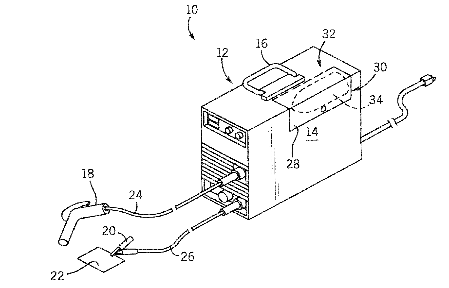
[0023] Referring now to FIG. 1, a perspective view of a welding device incorporating the present invention is shown. Welding device 10 includes a housing 12 enclosing the internal com...


PUM

PropertyMeasurementUnit
Electric potential / voltageaaaaaaaaaa
Poweraaaaaaaaaa

Abstract

A welder having an integrated gas cylinder is disclosed. The welder has a power source constructed to condition and output an electrical signal suitable to welding and a gas cylinder disposed in an enclosure.

Description

BACKGROUND OF INVENTION [0001] The present invention relates generally to welding systems and, more particularly, to a welder having an integrated gas cylinder. [0002] Welder power sources have become increasingly portable in recent years. This portability is largely the result of lighter unit weight and improved electrical components. One advancement in the area of electrical components has been the incorporation of inverter-type power sources. The application of an inverter power source has reduced the size and weight of welders and created usable space within the confines of the housing, while maintaining the ability to generate the outputs required for welding. Similarly, advances in battery technology allow the incorporation of an energy storage device in a welder to allow easy transport. [0003] Improvements in wire feeder technology have also improved the ease of use and portability of a welder. Wire welding is generally believed to be easier to learn than conventional stick w...

Claims


Application Information

Patent Timeline
IPC IPC(8): B23K9/173B23K9/32
CPCB23K9/173F17C2205/0373B23K9/325
Inventor ALBRECHT, BRUCESTANZEL, KENVOGEL, BERNARD J.
Owner ILLINOIS TOOL WORKS INC
Why Eureka
Try Eureka