
Friction stir tool for friction welding

a technology of friction stir welding and stir welding, which is applied in the direction of automatic control devices, precision positioning equipment, and soldering auxilary devices, etc., can solve the problems of impaired measurement accuracy of measuring methods, inability to determine the temperature of stirred materials in the weld zone with sufficient accuracy, etc., and achieve the effect of sufficient measuring accuracy

Inactive Publication Date: 2005-01-06
EADS DEUT GMBH
View PDF4 Cites 36 Cited by
  • Summary
  • Abstract
  • Description
  • Claims
  • Application Information

AI Technical Summary

Benefits of technology

The present invention is about a friction stir welding tool for friction welding. The invention aims to create a tool that can control the welding procedure based on the temperature in the weld zone. The invention uses a temperature measuring device that records the temperature of the weld zone by measuring the temperature of the pin of the friction stir welding tool. The measuring device is placed close enough to the weld zone to ensure accurate temperature readings. This allows for better control of the welding process and ensures quality welds.

Problems solved by technology

Since the plates cool off considerably a short distance from the weld zone, the temperature of the stirred material of the weld zone cannot be determined with sufficient accuracy with this measuring process.
As an optical radiation measurement, this measuring method is impaired in its measurement accuracy by the structured surface of the welding location.

Method used


Image

  • Friction stir tool for friction welding
  • Friction stir tool for friction welding

Examples


Embodiment Construction

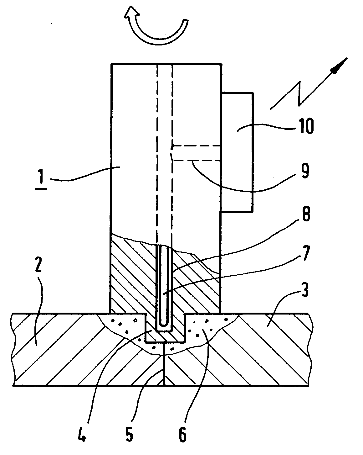
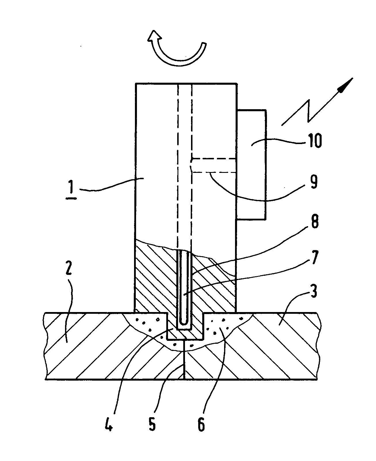
[0013] Two plates 2 and 3 that come into blunt contact with each other are welded together, for example, with the friction stir welding tool 1. The pin 4 of the friction stir welding tool is frictioned into the two plates 2 and 3 by means of a pressure, rotation, and forward motion of the stirring tool in a known manner, along the contact joint 5. After cooling, the stirred material forms the weld seam in the weld zone 6 that is produced in this manner.

[0014] The stirring tool 1 is provided with a blind bore 8, which ends in a pin 4, and wherein a temperature sensor 7 can be accommodated. The electric connections for the sensor are guided via a radial bore 9 to a telemetric measuring system 10, which is arranged on the surface of the stirring tool underneath its clamping area.

[0015] The temperature sensor 7 can be configured, for example, as a standard thermal element. An electronic evaluation system for the thermal element and a transmitter equipped with a suitable receiver for t...


PUM

PropertyMeasurementUnit
temperatureaaaaaaaaaa
temperature sensoraaaaaaaaaa
vertical pressureaaaaaaaaaa

Abstract

The object of the invention is to create a friction welding tool for friction welding that can be controlled with respect to measuring accuracy based upon the temperature in the weld zone. This object is attained in accordance with the invention by determining the temperature values of the weld zone (6) by means of a temperature sensor (7), which is arranged with its measuring point in the pin (4) of the stir welding tool (1).

Description

BACKGROUND AND SUMMARY OF THE INVENTION [0001] The present invention concerns a friction stir welding tool for friction welding. [0002] A friction welding process is described, for example, in international publication WO 95 / 26254 A1. To produce a good welded connection, this publication discloses guiding a friction stir welding tool with vertical pressure along the connecting point of the workpiece to be welded. It is particularly advantageous to provide the friction stir welding tool with a concave shoulder and a pin configured in a screw shape. [0003] Also of great importance in friction stir welding is the adjustment of a temperature that is suitable for the welding procedure in the stirred material of the weld zone. This temperature is influenced, among other things, by the parameters of the welding process, such as the rate of feed, the number of revolutions, and the contact pressure of the friction stir welding tool. Also known is a process of influencing by means of cooling ...

Claims


Application Information

Patent Timeline
Patent Type & Authority Applications(United States)
IPC IPC(8): B23K20/12
CPCB23K20/1235B23K2201/32B23K20/1255B23K2101/32
Inventor RAETHER, KLAUSSILVANUS, JUERGENZIMMERMANN, WERNER
Owner EADS DEUT GMBH
Learn More