Control device with blockable attachment places

a control device and attachment place technology, applied in the field of control devices, can solve problems such as safety operation malfunction and faulty measuremen

Active Publication Date: 2005-01-06
ROBERT BOSCH GMBH
View PDF29 Cites 0 Cited by
  • Summary
  • Abstract
  • Description
  • Claims
  • Application Information

AI Technical Summary

Benefits of technology

[0004] Accordingly, it is an object of the present invention to provide a control device with blockable attachment places, which avoids the disadvantages of the prior art.

Problems solved by technology

A false installation position leads to faulty measurements and to a malfunction of the safety operation.

Method used


Image

  • Control device with blockable attachment places
  • Control device with blockable attachment places

Examples


Embodiment Construction

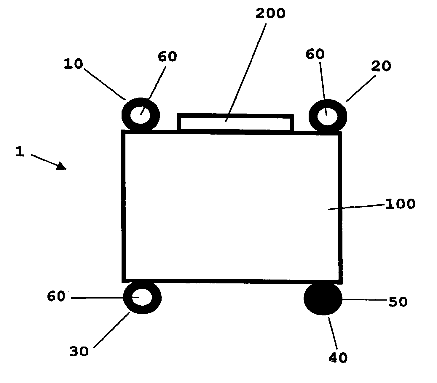
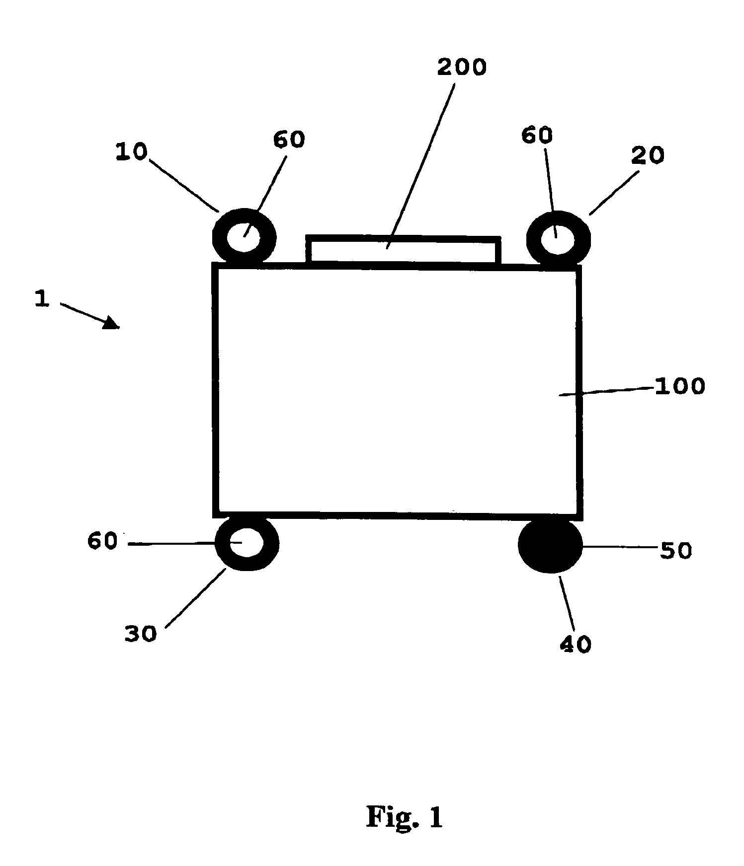
[0016] An inventive control device is shown in FIG. 1 and identified as a whole with reference numeral 1. The control device has a housing 100. The housing is rectangular and has four possible attachment places each arranged on a respective longitudinal side of the housing in a corresponding corner region.

[0017] A plug 200 is arranged on one longitudinal side of the housing 10 between two attachment places 10 and 20. An attachment place 40 is provided on a longitudinal side of the housing 100, which is opposite to the plug 200. The attachment place 40 is formed as a blocking attachment place 50. The blocking attachment place 50 is closed and unsuitable for receiving an attachment means. The remaining three attachment places 10, 20, 30 have recesses for receiving an attachment means.

[0018] The arrangement of the possible attachment places is formed so that with a “key-lock” principle, an exchange during the mounting is excluded. Thereby similar devices can not be installed in an er...


PUM


Abstract

A control device has a plurality of possible attachment places for receiving attachment elements at least one of the attachment places being formed as a blocking attachment place which prevents receiving of an attachment element.

Description

BACKGROUND OF THE INVENTION [0001] The present invention relates to a control device with several possible attachment places for receiving of attachment means. [0002] The customers catalog “Auslöseeinheit Rückhalte System” (ARS), Arbeitskreis ARS, Sep. 17, 1993 discloses a control device with attachment places. The sensor system of such a control device has the function of monitoring the travel-dynamic condition of a vehicle and adjust to the corresponding installation location with respect to the vehicle axes. A false installation position leads to faulty measurements and to a malfunction of the safety operation. In order to guarantee a correct installation position, the so-called customer catalog provides a control device with three asymmetrically arranged attachment places. An installation platform with three attachment pins which correspond to the attachment places is mounted as a counter piece to the control device in the motor space of a vehicle. Due to the asymmetrical arrang...

Claims


Application Information

Patent Timeline
Patent Type & Authority Applications(United States)
IPC IPC(8): B60R16/02B60R11/00B60R11/02B60R21/01B60R21/16
CPCB60R11/00B60R11/0264B60R2011/0038Y10T403/125Y10T403/1616Y10T403/20B60R2021/01006
Inventor JAKOB, GERTECKERT, BERND
Owner ROBERT BOSCH GMBH
Why Eureka
Try Eureka