Braking stroke simulator

a technology of braking stroke and simulator, which is applied in the direction of braking system, braking components, transportation and packaging, etc., can solve the problems of increasing cost, unable to ensure the proper feeling of the brake pedal, and no hysteresis, and achieves stable initial load and little age deterioration

Active Publication Date: 2005-01-06
ADVICS CO LTD
View PDF20 Cites 23 Cited by
  • Summary
  • Abstract
  • Description
  • Claims
  • Application Information

AI Technical Summary

Benefits of technology

[0009] Accordingly, it is an object of the present invention to provide a braking stroke simulator used for a component of a hydraulic brake system for a vehicle, which

Problems solved by technology

However, when the travel of the master piston begins to produce its stroke by means of the simulator spring element made of the spring, almost no hysteresis is provided, so that the proper brake pedal feeling can not be ensured.
In addition, as the initial load applied to the simulator spring element made of rubber is set independently, severe dimensional accuracy of t

Method used


Image

  • Braking stroke simulator
  • Braking stroke simulator
  • Braking stroke simulator

Examples


Embodiment Construction

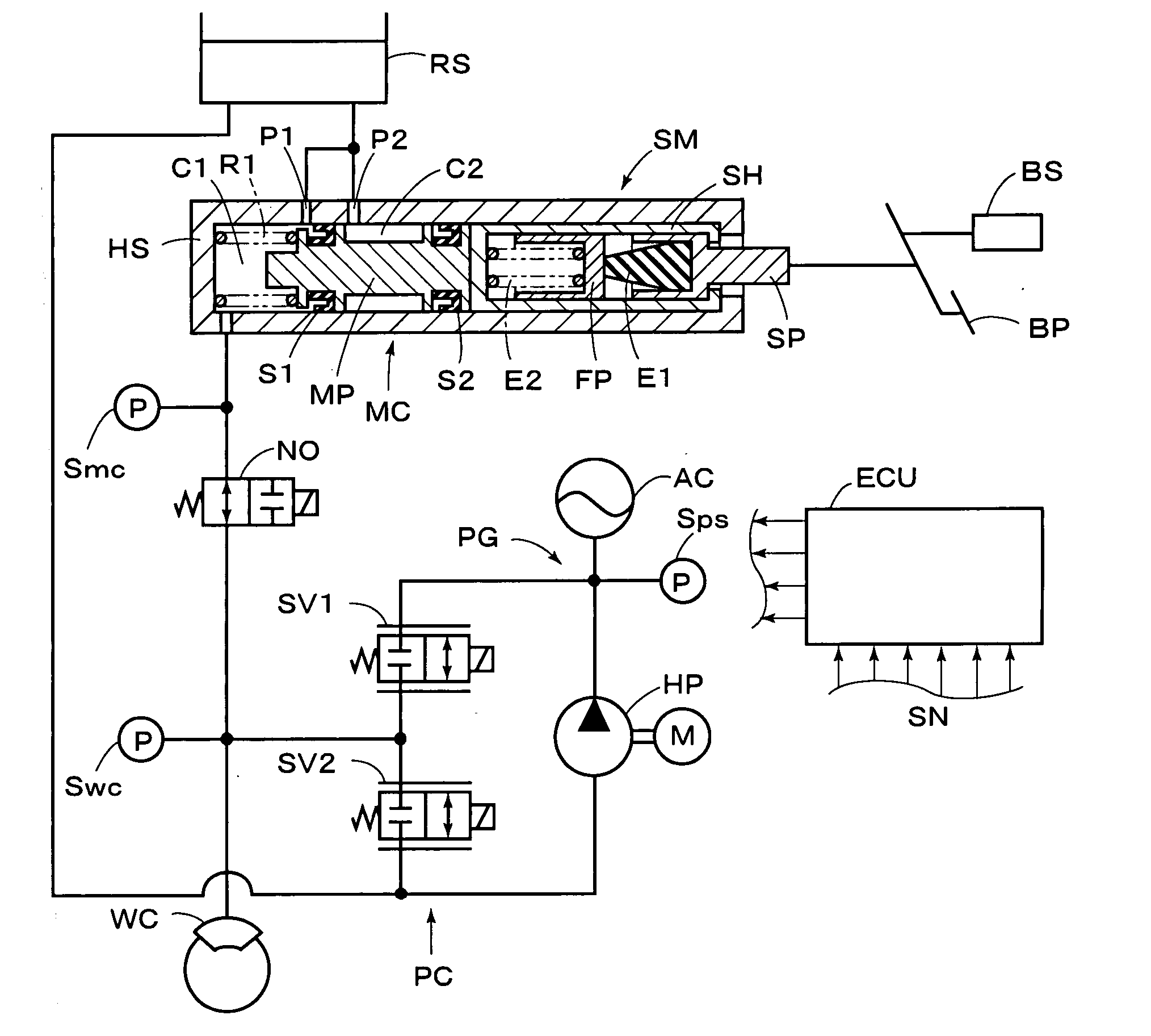
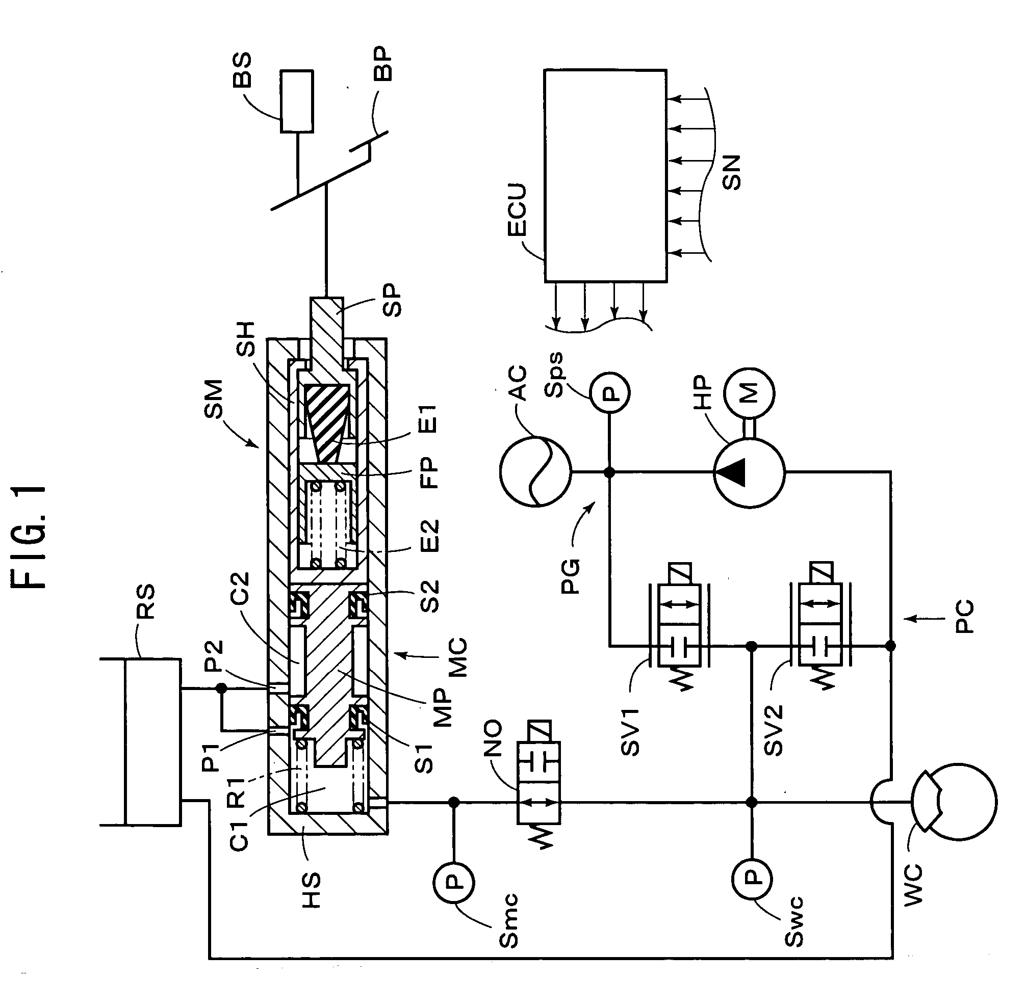
[0020] Referring to FIG. 1, there is illustrated a hydraulic brake system for a vehicle having a braking stroke simulator according to an embodiment of the present invention. A stroke simulator SM has a housing HS which accommodates a simulator piston SP moved in response to operation of a brake pedal BP, which is served as a manually operated braking member, and a first elastic member E1 and a second elastic member E2 for providing a stroke to the simulator piston SP in response to braking operation force. In the housing HS, a master piston MP and a return spring R1 are accommodated to constitute a master cylinder MC, which serves as a pressure generating device for generating hydraulic pressure in response to operation of the brake pedal BP, when a pressure control device PC as described later comes to be abnormal, to supply the hydraulic pressure into wheel brake cylinders (indicated by WC), each of which is operatively mounted on each wheel of the vehicle. And, a normally open e...


PUM


Abstract

The present invention is directed to a braking stroke simulator for use in a brake system, which comprises a simulator piston moved in response to operation of a manually operated braking member, and an elastic element for providing a stroke to the simulator piston in response to braking operation force applied to the manually operated braking member, wherein restoring amount of the elastic element is restricted to set an initial load to be applied thereto. The elastic element includes a first elastic member made of rubber, and a second elastic member made of a helical spring, which is disposed in series with the first elastic member. The initial load applied to the first elastic member and the initial load applied to the second elastic member are set to be substantially equal to each other.

Description

[0001] This application claims priority under 35 U.S.C. Sec.119 to No.2003-135981 filed in Japan on May 14, 2003, the entire content of which is herein incorporated by reference. BACKGROUND OF THE INVENTION [0002] 1. Field of the Invention [0003] The present invention relates to a braking stroke simulator for use in a hydraulic brake system of a vehicle, and more particularly to a braking stroke simulator operated in response to operation of a manually operated braking member. [0004] 2. Description of the Related Arts [0005] Heretofore, there is known various hydraulic brake systems, including such a system as constituted by a hydraulic pressure control device having a pressure source for regulating hydraulic pressure discharged from the pressure source in response to operation of the manually operated braking member, to supply it into wheel brake cylinders. And, a braking stroke simulator is disposed to provide a stroke of the manually operated braking member in response to the bra...

Claims


Application Information

Patent Timeline
IPC IPC(8): B60T8/17B60T8/40B60T11/18B60T13/12B60T13/74B60T17/04
CPCB60T8/4081B60T17/04B60T13/74B60T8/409
Inventor KUSANO, AKIHITO
Owner ADVICS CO LTD
Why Eureka
Try Eureka