Projection type image display apparatus and image display system

a projection type and image display technology, applied in the field of projection type image display apparatus, can solve the problems of difficult to efficiently use the pupil of an axially symmetric optical system, large reduction of luminance, and high heat generation of light sources, so as to reduce the flickering of projected images and the amplitude of power supply capacity, the effect of suppressing the deterioration of the luminous efficiency of organic el elements

Inactive Publication Date: 2005-05-10
CANON KK
View PDF9 Cites 19 Cited by
  • Summary
  • Abstract
  • Description
  • Claims
  • Application Information

AI Technical Summary

Benefits of technology

[0017]An object of the invention is to obtain an effect of suppressing deterioration in luminous efficiency of organic EL elements due to luminance modulation of pixels in response to pulse intermittent turning-on drive, and to reduce flickering of projected images and amplitude of the power supply capacity.
[0018]Furthermore, another object of the invention is to provide a projection type image display apparatus having little deterioration in photoelectric conversion efficiency of organic EL elements which can individually modulate pixels.

Problems solved by technology

In the case of liquid crystals, unnecessary illumination light exists due to the light transmittance, the aperture efficiency of each pixel or accuracy of polarization control.
Furthermore, in the case of the micromirror device, it is difficult to efficiently use the pupil of an axially symmetric optical system depending on the aperture efficiency of each pixel and the numerical aperture of a projection lens due to oblique -incidence illumination and the numerical aperture of an illumination system.
Therefore, in order to make a displayed image brighter, a metal halide and a high-pressure mercury lamp is used as a light source, however, a high voltage is required as a light source voltage, so that the light source generates high heat.
However, after the organic EL elements continuously emit light at a high luminance, luminance greatly lowers.
One of the causes of this problem is that heat is generated due to a current supplied for driving the organic EL elements, accumulates, and raises the element temperature, and this deteriorates the structure and characteristics of the organic thin films and gradually lowers luminous efficiency.
Furthermore, a possible cause of efficiency lowering of the organic EL elements is as follows.
Among these, as a main cause of deterioration concerning the speed of chemical reaction, there is deterioration acceleration due to a self-raising temperature parameter according to heat energy generation in a photoelectric converting process.
Therefore, when emission driving is carried out in a low-power supplied condition at a low temperature, the speed of changing the photoelectric conversion efficiency slows and lengthens the life.
However, as the power to be supplied is increased to increase the emission intensity, the photoelectric conversion efficiency exponentially lowers, resulting in a short life of the element.
Therefore, nonconformity occurs in that the quality stability lowers as it is attempted to achieve brighter and higher-quality image display.
For example, in a high-temperature high-humidity environment, for example, at a temperature of 30° C. and a humidity of 80%, water vapor condenses into dew condensation on the EL elements, and when waterdrops are generated in the light emission direction, it becomes impossible that an image to be displayed by the EL elements is projected as it is by a projection lens, resulting in a distorted image being projected.

Method used


Image

  • Projection type image display apparatus and image display system
  • Projection type image display apparatus and image display system
  • Projection type image display apparatus and image display system

Examples


embodiment 1

[0042

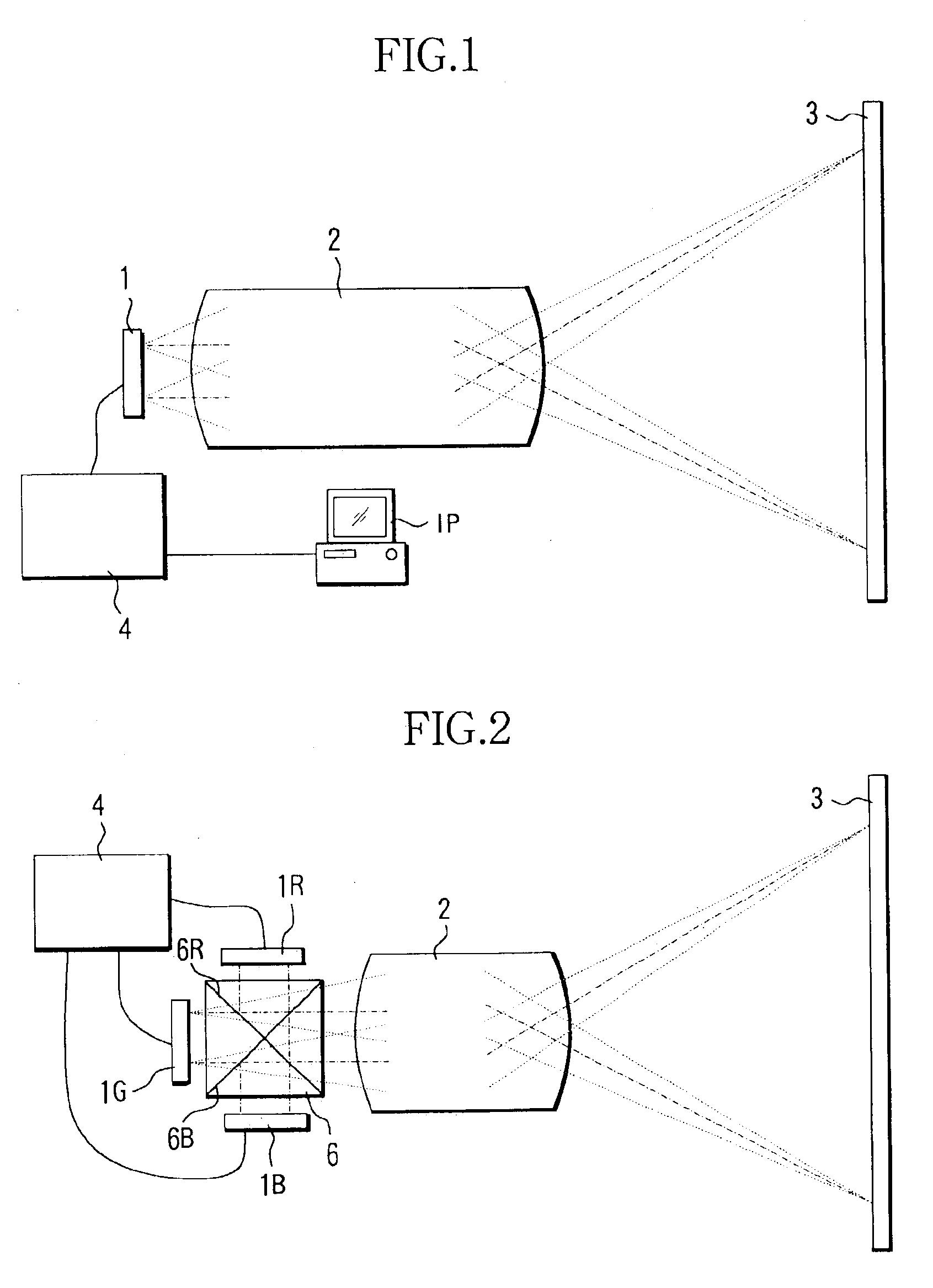
[0043]FIG. 1 is a sectional view of a main optical system forming a projector (projection type image display apparatus) of Embodiment 1 of the present invention.

[0044]An EL element 1 emits light including image information. This EL element 1 comprises a plurality of pixels which emit image information as emission pattern information.

[0045]A controller 4 comprises a CPU, etc., which electrically controls the EL element 1 in response to image signals from an image signal providing apparatus IP such as a personal computer, a DVD player, a VCR, a video camera, a television, or a unit of an antenna to receive image signal and a tuner (the same applies to the next Embodiment 2 although it is not shown). The EL element 1 emits light based on electrical signals from the controller 4.

[0046]Light emitted from the EL element 1 is projected onto a screen 3 by a projection lens 2. The screen 3 has light diffusibility on its surface, and an observer recognizes an image by viewing the light d...

embodiment 2

[0047

[0048]FIG. 2 is a sectional view of a main optical system forming a projector (projection type image display apparatus) of Embodiment 2 of the present invention.

[0049]EL elements 1R, 1G, and 1B emit light in colors administering the three additive primary colors of red, green, and blue. Each of these EL elements 1R, 1G, and 1B comprises a plurality of pixels which emit image information as light emission pattern information.

[0050]A controller 4 transmits electrical signals to the EL elements 1R, 1G, and 1B in response to inputted image signals from the image signal providing apparatus (denoted by IP in Embodiment 1) to control these EL elements 1R, 1G, and 1B. Based on electrical signals from the controller 4, each of the EL elements 1R, 1G, and 1B emits light in a color that the corresponding EL element handles.

[0051]Light emitted from the EL element 1 is color-combined by a wavelength-combining prism (color-combining prism) 6. The wavelength-combining prism 6 is generally cal...

embodiment 3

[0088

[0089]FIG. 9 shows a main optical system forming a projector (projection type image display apparatus) of Embodiment 3 of the present invention.

[0090]In this figure, an electroluminescence (EL) element 101 emits light containing image information. This EL element 101 comprises a plurality of pixels which emit light so as to express image information as light emission pattern information.

[0091]The EL element 101 is electrically controlled based on electrical signals from a display controller 154. Image signals are inputted into the display controller 154 from an image signal providing apparatus IP such as a personal computer, a DVD player, a VCR, a video camera, a television, or a unit of an antenna to receive image signal and a tuner. The controller 154 provides electrical signals for making the EL element 101 to carry out emission based on inputted image signals and to display an image to the EL element 101 (the same applies to the next Embodiment 4 although it is not shown). ...


PUM

PropertyMeasurementUnit
humidityaaaaaaaaaa
temperatureaaaaaaaaaa
thicknessaaaaaaaaaa

Abstract

A projection type image display apparatus which suppresses deterioration in luminous efficiency of an organic EL element and reduces flickering of projected images and an amplitude of a power supply capacity is disclosed. The apparatus comprises an electroluminescence (EL) element, a projection optical system, and a controller which generates drive signals to control the emission amount from the EL element. An EL material used for a luminescent layer of the EL element is a phosphorescent material which emits phosphorescence by priority, which is emitted from an excited triplet state. The controller generates drive signals by superimposing an intermittent turning-on signal on emission amount modulating signals to modulate current values to be injected into pixels according to display image signals.

Description

BACKGROUND OF THE INVENTION[0001]1. Field of the Invention[0002]The present invention relates to a projection type image display apparatus such as a projector, etc.[0003]2. Description of Related Art[0004]Conventionally, a projection type image display apparatus uses a liquid crystal panel or a micromirror device as a light modulation device for switching, and displays an image on a screen by projecting a light pattern selected upon controlling light transmission and shielding or polarization.[0005]However, in the abovementioned display, when a liquid crystal panel or a micromirror device is used as a light modulation device, it is necessary that shielded light is removed as unnecessary energy by being absorbed by a polarizer or a light absorbing medium.[0006]In the case of liquid crystals, unnecessary illumination light exists due to the light transmittance, the aperture efficiency of each pixel or accuracy of polarization control. Furthermore, in the case of the micromirror device...

Claims


Application Information

Patent Timeline
Patent Type & Authority Patents(United States)
IPC IPC(8): G09G3/32H04N5/74H04N5/70G09G3/00H04N9/31
CPCG09G3/002G09G3/2011G09G3/3216H04N9/3138H04N5/70H04N5/74H04N5/7408H04N9/31G09G2320/0247G09G2320/043G09G2330/025G09G2330/021
Inventor KOIDE, JUN
Owner CANON KK
Why Eureka
Try Eureka