Reciprocating linear actuator

a linear actuator and reciprocating technology, applied in the direction of dynamo-electric machines, electrical apparatus, propulsion systems, etc., can solve the problems of difficult to reduce the size and difficulty in reducing the size of the reciprocating linear actuator, and achieve the effect of less variation, less variation, and less variation

Inactive Publication Date: 2005-01-06
MATSUSHITA ELECTRIC WORKS LTD
View PDF2 Cites 5 Cited by
  • Summary
  • Abstract
  • Description
  • Claims
  • Application Information

AI Technical Summary

Benefits of technology

[0015] Preferably, the connection bodies are connected to the movable elements on alignment planes of the movable elements so as to be symmetrical about a middle point between the movable elements. This allows the movable elements to perform a well-balanced reciprocating motion with relatively less variation.
[0016] Mounting positions of the connection body to the respective movable elements may be on reciprocating directions of centers of gravity of the movable elements. This allows the movable elements to perform a well-balanced reciprocating motion with relatively less variation as well as preventing rotational moment and accompanying stress from being generated on the connection body when the movable element changes its position in the reciprocating direction, and thus to enhance the reliability of the connection body.
[0017] Mounting positions of the connection body to the respective movable elements may be on alignment planes of the movable elements at a uniform distance from centers of gravity of the respective movable elements or may be on a plane that is orthogonal to alignment planes of the movable elements and parallel to the reciprocating direction as well as including centers of gravity of the movable elements, at a uniform distance from the cen

Problems solved by technology

However, the construction in which the connection body formed of the coiled spring is disposed between the movable elements requires a considerable space, thus making it difficult to r

Method used


Image

  • Reciprocating linear actuator
  • Reciprocating linear actuator
  • Reciprocating linear actuator

Examples


embodiment 1

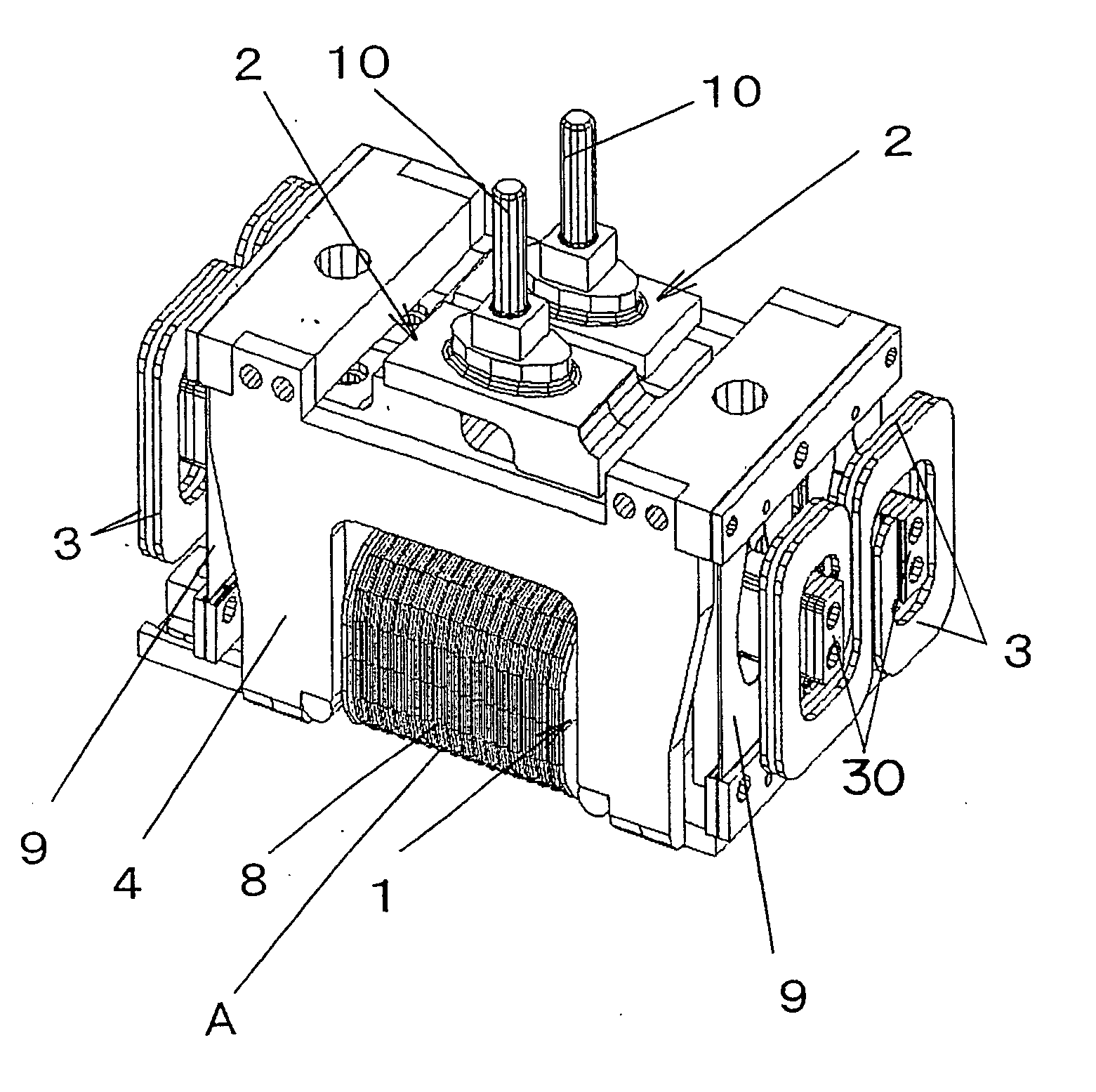
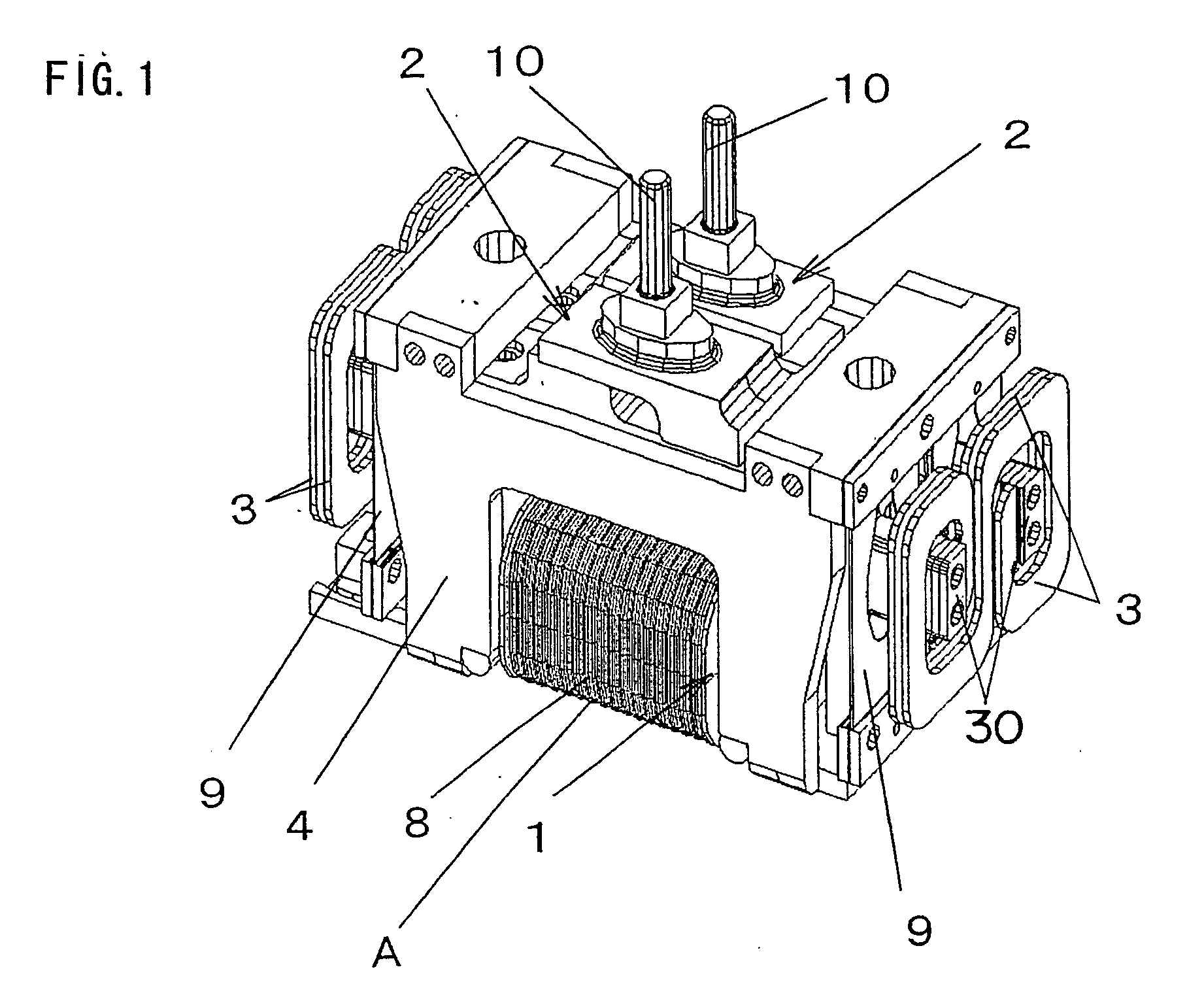
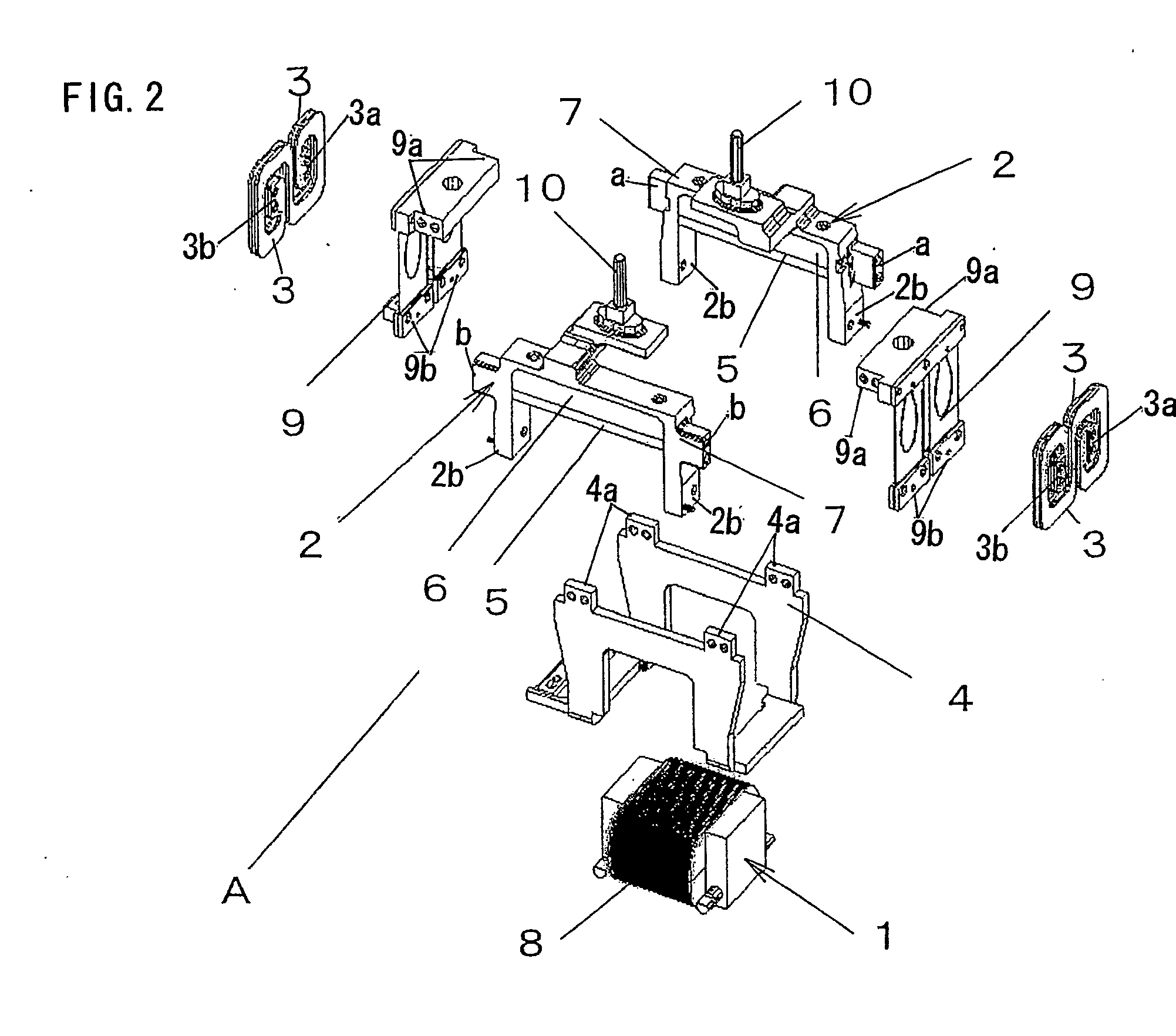
[0038] FIGS. 1 to 4 show a reciprocating linear actuator A, which is used as a drive source for a reciprocatory electric shaver, according to Embodiment 1. This actuator A comprises a stator 1, movable elements 2, a chassis 4, and a connection body 3 connecting the two movable elements 2 and 2.

[0039] The movable element 2 has a permanent magnet 5 and a yoke 6 (back yoke), which are constructed as a unit with a frame member 7. The permanent magnet 5 is bonded to the yoke 6 which is formed from a magnetic material. Further, the movable element 2 has a connection portion 10 to which the movable cutter of an electric shaver is connected.

[0040] The stator 1 is an electromagnet in which a winding 8 is wound around a core, which is a sintered body of magnetic material or a laminated core of iron as magnetic material, and the stator is secured to the chassis 4 with a screw or the like.

[0041] The movable element 2 is suspended from the chassis 4 via a suspension piece 9 made of a flat spr...

embodiment 2

[0050]FIGS. 5 and 6 show a reciprocating linear actuator according to Embodiment 2. A connection body 3 used in this embodiment is a reverse U-shaped flat spring of which the two ends further extends inward to be connected to the respective movable elements 2 and 2. This connection body 3 also has such a shape that can be drawn with a single stroke on a plane orthogonal to the reciprocating direction of the movable element 2. While the S-shaped connection body in the above embodiment is symmetrical about a point, the connection body 3 in this embodiment is symmetrical about a line, so that it is not directional in shape for facilitating the assembling. The mounting positions 30 of the connection body 3 to the respective movable elements 2 are on the alignment planes of the movable elements 2 at a uniform distance from the centers of gravity G of the respective movable elements 2. Although the mounting position 30 of the connection body 3 is not on the reciprocating direction of the ...

embodiment 3

[0051]FIGS. 7 and 8 show a reciprocating linear actuator according to Embodiment 3. A connection body 3 used in this embodiment has a S-shaped configuration, in which the two arched ends extend circumferentially to be connected to the respective movable elements 2 and 2. This connection body 3 has such a shape that can be drawn with a single stroke on a plane orthogonal to the reciprocating direction of the movable element 2. The mounting positions 30 of the connection body 3 to the respective movable elements 2 are on the plane (horizontal broken line in FIG. 8) that is orthogonal to the alignment plane of the movable element 2 and parallel to the reciprocating direction as well as including the centers of gravity G of the two movable elements 2. Further, the mounting positions are at a uniform distance from the centers of gravity G of the respective movable elements 2. Although the mounting position 30 of the connection body 3 is not on the reciprocating direction of the center of...


PUM


Abstract

A reciprocating linear actuator capable of reciprocatingly driving a plurality of movable elements (2 and 2) by a single stator (1). The movable elements (2 and 2) are connected to each other through a connection body (3) having a spring characteristic to be capable of displacement in the reciprocating direction of the movable element. The connection body (3) has such a shape that can be drawn with a single stroke on a two dimensional plane, and at least both ends thereof are connected to the movable elements (2 and 2), respectively. Since the connection body (3) is made of a flat spring, it requires less space for installation as compared to a connection body formed of a coiled spring. Further, since the entire connection body has an effective spring characteristic, a relatively smaller size is required for the connection body to provide a required spring characteristic. The less installation space for the connection body (3) is advantageous to a reduction in size of the linear actuator.

Description

TECHNICAL FIELD [0001] The present invention relates to a reciprocating linear actuator that can be used as a drive source for a reciprocatory electric shaver or the like. BACKGROUND ART [0002] Reciprocating linear actuators have been used as a drive source for a reciprocatory electric shaver (see, for example, Japanese laid-open patent publication No. HEI 7-313746). Such a reciprocating linear actuator (reciprocating motor) includes a stator and a plurality of movable elements that perform a reciprocating motion relative to the stator. The plurality of movable elements are associated with respective movable cutters of a plurality of cutter heads and configured to be driven by the single stator. Disposed between the plurality of movable elements is a connection body formed of a coiled spring. When reciprocating displacement amount of one of the movable elements is going to abruptly decrease due to a heavy load applied thereto, the connection body allows the decrease to be stopped by...

Claims


Application Information

Patent Timeline
IPC IPC(8): H02K33/02H02K33/16
CPCH02K33/16H02K33/02H02K41/03
Inventor FUJIWARA, MAKOTONAKAYAMA, SATOSHISANEMATSU, WATARU
Owner MATSUSHITA ELECTRIC WORKS LTD
Why Eureka
Try Eureka