Charge control of micro-electromechanical device

a micro-electromechanical and charge control technology, applied in static indicating devices, instruments, polarising elements, etc., can solve the problems of limiting the potential utility of the mems device and reducing the useable operating rang

Inactive Publication Date: 2005-01-06
MARTIN ERIC T +5
View PDF30 Cites 346 Cited by
  • Summary
  • Abstract
  • Description
  • Claims
  • Application Information

AI Technical Summary

Benefits of technology

One aspect of the present invention provides a charge control circuit for controlling a micro-electromechanical system (MEMS) device having variable capacitor formed by a first conductive plate and a second conductive plate separated by a variable gap distance. The charge control circuit comprises a switch circuit configured to receive a reference voltage having a selected voltage level and configured to respond to an enable signal having a duration at least as long as an electrical time constant constant of the MEMS device, but shorter than a mechanical time constant of the MEMS device, to apply the selected voltage level across the first and second plates for the duration to thereby cause a stored charge having a desired magnitude to accumulate on the variable capacitor, wherein the variable gap distance is a function of the magnitude of the stored charge.

Problems solved by technology

However, this approach suffers from electrostatic instability that greatly reduces a useable operating range over which the gap distance can be effectively controlled.
This non-linear relationship between the control voltage and the gap distance limits the controllable range of electrode movement to only about one-third of the initial gap distance, and thus limits the potential utility of the MEMS device.

Method used


Image

  • Charge control of micro-electromechanical device
  • Charge control of micro-electromechanical device
  • Charge control of micro-electromechanical device

Examples


Embodiment Construction

In the following detailed description of the preferred embodiments, reference is made to the accompanying drawings which form a part hereof, and in which is shown by way of illustration specific embodiments in which the invention may be practiced. It is to be understood that other embodiments may be utilized and structural or logical changes may be made without departing from the scope of the present invention. The following detailed description, therefore, is not to be taken in a limiting sense, and the scope of the present invention is defined by the appended claims.

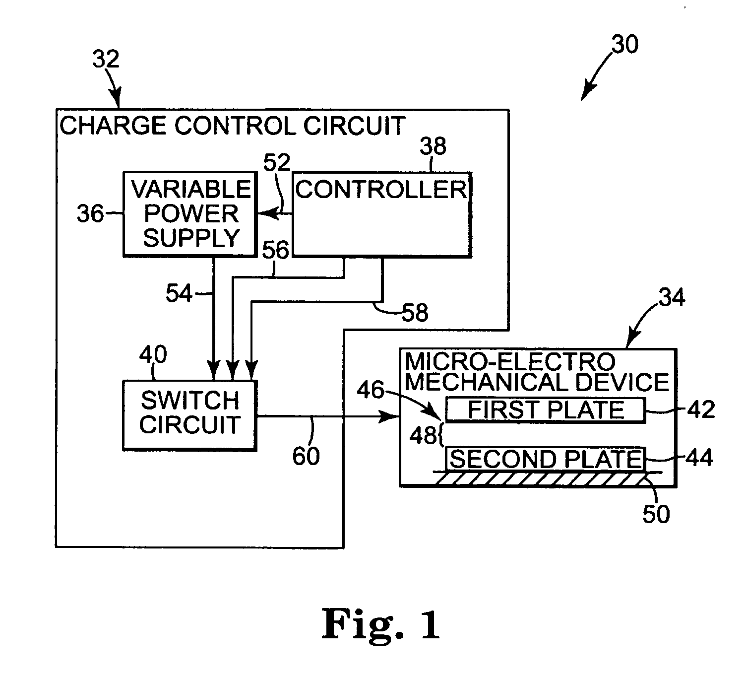
FIG. 1 is a diagram illustrating an exemplary embodiment of a micro-electromechanical system 30 according to the present invention. The micro-electromechanical system 30 includes a charge control circuit 32 and a micro-electromechanical device 34. Charge control circuit 32 further includes a variable power supply 36, a controller 38, and a switch circuit 40. In the exemplary embodiment, micro-electromechanical device...


PUM


Abstract

A charge control circuit for controlling a micro-electromechanical system (MEMS) device having variable capacitor formed by first conductive plate and a second conductive plate separated by a variable gap distance. The charge control circuit comprises a switch circuit configured to receive a reference voltage having a selected voltage level and configured to respond to an enable signal having a duration at least as long as an electrical time constant constant of the MEMS device, but shorter than a mechanical time constant of the MEMS device, to apply the selected voltage level across the first and second plates for the duration to thereby cause a stored charge having a desired magnitude to accumulate on the variable capacitor, wherein the variable gap distance is a function of the magnitude of the stored charge.

Description

THE FIELD OF THE INVENTION The present invention relates to the field of micro-electromechanical devices. More particularly, the present invention relates to charge control of a micro-electromechanical device. BACKGROUND OF THE INVENTION Micro-electromechanical systems (MEMS) are systems which are developed using thin film technology and which include both electrical and micro-mechanical components. MEMS devices are used in a variety of applications such as optical display systems, pressure sensors, flow sensors and charge control actuators. MEMS devices use electrostatic force or energy to move or monitor the movement of micro-mechanical electrodes which can store charge. In one type of MEMS device, to achieve a desired result, a gap distance between the electrodes is controlled by balancing an electrostatic force and a mechanical restoring force. Digital MEMS devices use two gap distances, while analog MEMS devices use multiple gap distances. MEMS devices have been developed us...

Claims


Application Information

Patent Timeline
Patent Type & Authority Applications(United States)
IPC IPC(8): G02B26/06B81B3/00B81B7/04G02B5/30G02B26/00G09G3/34H01G5/16
CPCG02B26/001H01G5/16G09G2300/0809G09G3/3466
Inventor MARTIN, ERIC T.HUNTER, MARKPIEHL, ARTHURPRZYBYLA, JAMES R.GELHAUS, MATTHEWSZEPESI, LESLIE LOUIS JR.
Owner MARTIN ERIC T
Why Eureka
Try Eureka