Camera system for a motor vehicle
a camera system and motor vehicle technology, applied in the field of camera systems, can solve the problems of inability to prevent the obstruction of the camera field of view by fogging from inside, the solution is undesirably complex to implement, and the effect of not providing immediate reli
- Summary
- Abstract
- Description
- Claims
- Application Information
AI Technical Summary
Benefits of technology
Problems solved by technology
Method used
Image

Examples
first embodiment
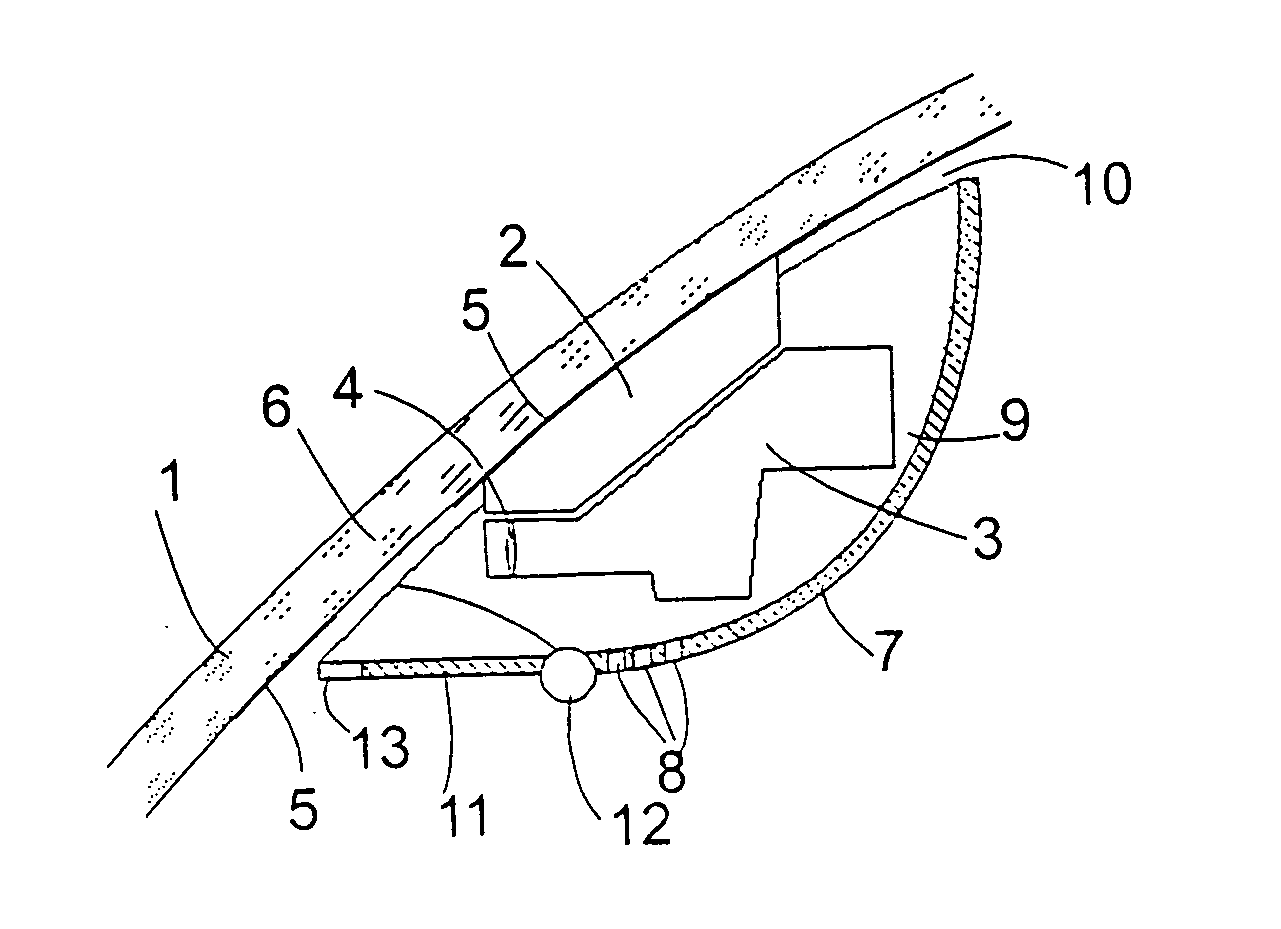
[0022]FIG. 1 shows a schematic section through a camera system according to the invention. A mounting bracket 2 is adhered to a windshield 1 of a motor vehicle, to which in turn an electronic camera 3 is secured. The camera 3, since it is so well known, is shown essentially schematically by its outline; basically it's front lens 4 is shown. The windshield 1 is, for its part, provided on its inner side with a black coating, which hides the camera system from the outside; essentially only a transparent window 6 is left free, through which the camera 3 can see the outside.
[0023] Towards the passenger compartment the camera 3 is covered by a shell-like housing 7, in the lower area of which a plurality of holes 8 are formed, which permit the inflow of fresh area into the inside of the housing 7 below the camera 3. The mounting bracket 2 is broader than the camera 3 itself in the direction transverse to the section plane of FIG. 1, and includes engagement means on (not shown) side flanks,...
third embodiment
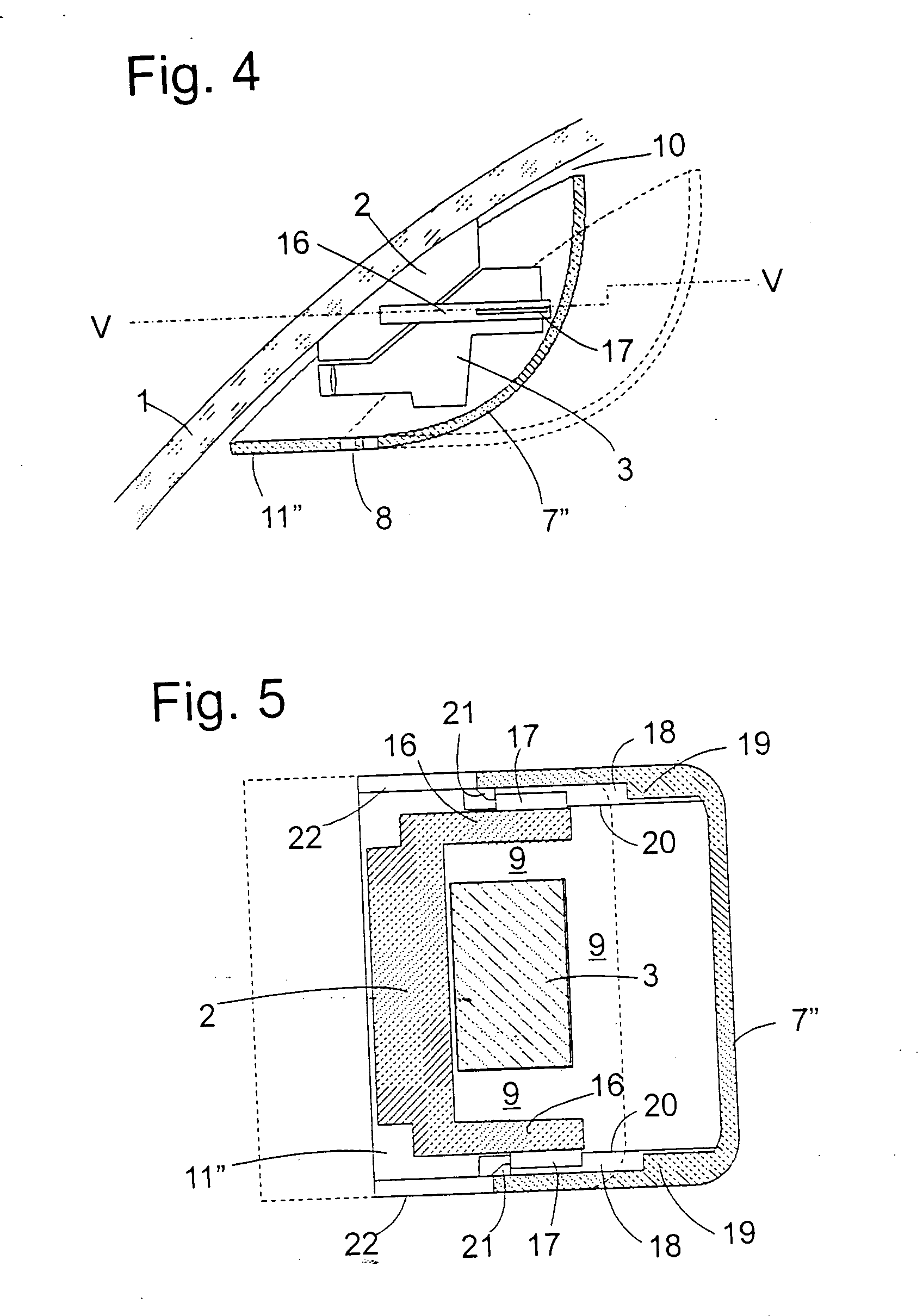
[0027]FIG. 4 shows the inventive camera system in a section analogous to FIGS. 1-3, wherein the housing 7″, which again together with the shield 11″ is fused into a single piece, is slideable on tracks between a closed position shown with continuous lines and an open position shown with dashed lines. These tracks are formed by two bracket arms 16 which, beginning from the mounting bracket 2, engage about two sides of the camera 3 and respectively have an outwardly oriented spring 17. The two springs 17 are, as can be seen in the horizontal section of FIG. 5, guided in the horizontal groove 18, which are respectively formed by two ribs 19, 20 projecting from the side flanks of the housing 7′. The two grooves 18 are respectively terminated by an abutment projection 21 at the front edge of the housing 7″ facing towards the windshield 1 which in the open position shown with solid lines in FIG. 5 respectively abut against one edge of the springs 17 and thus prevent a complete pulling off...
fourth embodiment
[0029]FIGS. 6 and 7 show the invention in two sections analogous to those of FIGS. 4 and 5. Housing 7″′ and shield 11″′ are here, again, formed as two parts, and this namely in the manner that the plate shaped shield 11″′ is guided in grooves 23 of a section 24 of the housing slidable between a (not shown) closed position, in which it is flush with and closes the cutout 24, and an open position shown in the Figs., in which it permits access to the window 6 and the front lens of the camera 3.
PUM
 Abstract
Description
Claims
Application Information
 - R&D
- Intellectual Property
- Life Sciences
- Materials
- Tech Scout
- Unparalleled Data Quality
- Higher Quality Content
- 60% Fewer Hallucinations
Browse by: Latest US Patents, China's latest patents, Technical Efficacy Thesaurus, Application Domain, Technology Topic, Popular Technical Reports.
© 2025 PatSnap. All rights reserved.Legal|Privacy policy|Modern Slavery Act Transparency Statement|Sitemap|About US| Contact US: help@patsnap.com