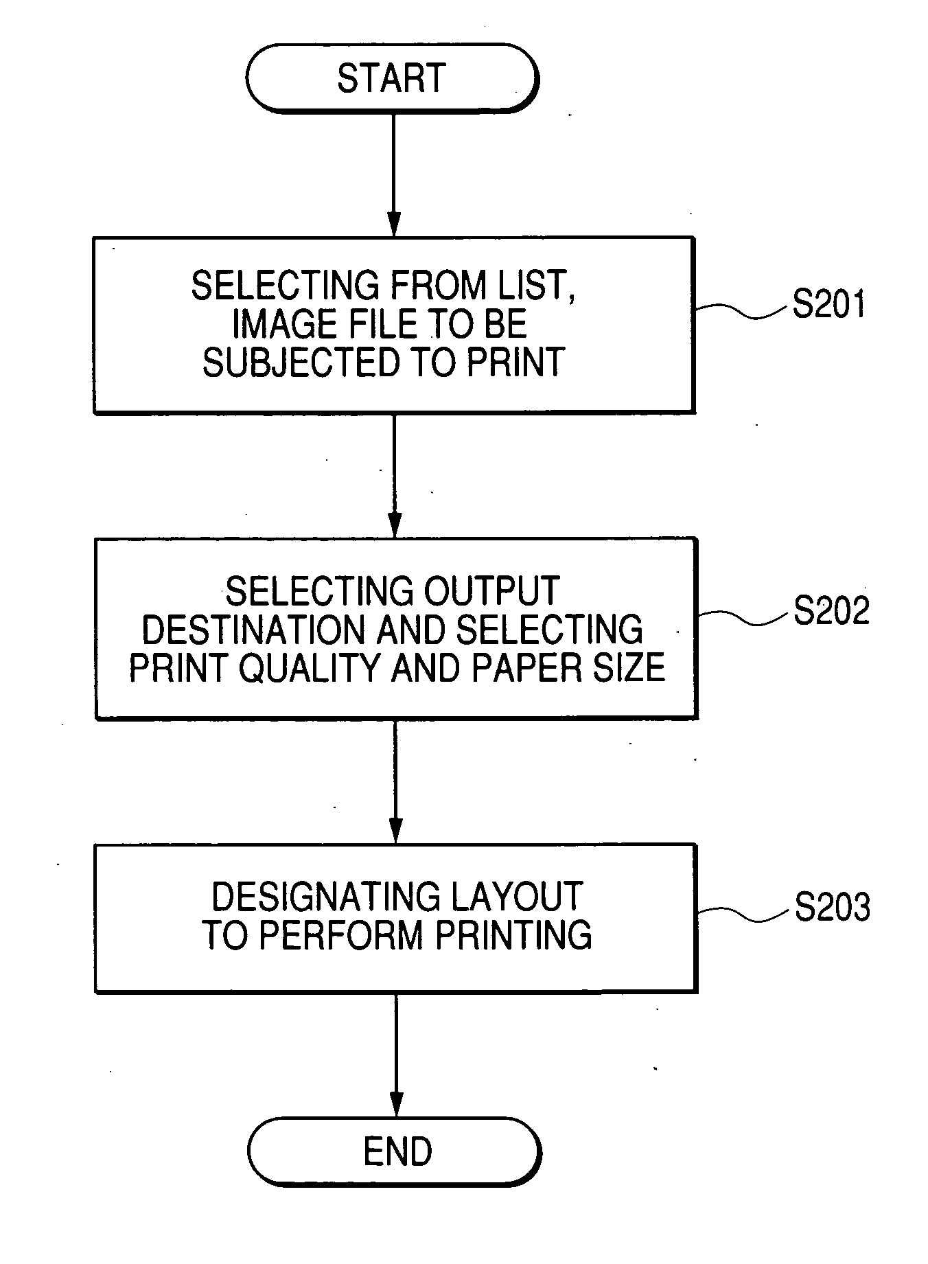
Printing method, printing apparatus, recording medium, and program
a printing apparatus and printing method technology, applied in the direction of digital output to print units, visual presentation using printers, instruments, etc., can solve the problems of user being required to perform printing, unable to easily overview which image is printed at which page, and no application which performs reduced display of all pages to overview printing, etc., to achieve the effect of simplifying the overview of printing results and easy to imagine printing results
- Summary
- Abstract
- Description
- Claims
- Application Information
AI Technical Summary
Benefits of technology
Problems solved by technology
Method used
Image
Examples
first embodiment
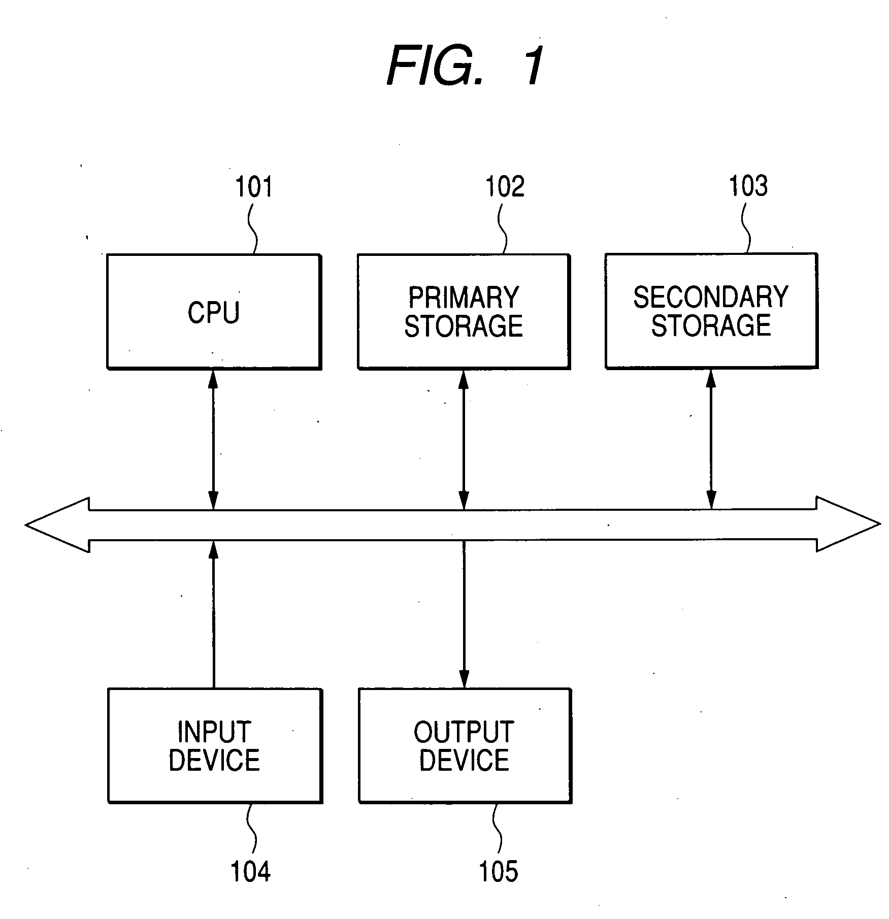
The present invention will be specifically described referring to the accompanying drawings. FIG. 1 shows an outline of the system realizing a first embodiment. CPU 101 controls an overall operation of the system and performs execution of the program stored in a primary storage 102 and the like. The primary storage 102 is a memory which reads the program stored in a secondary storage 103 and stores the read program. The secondary storage 103 may be, e.g. a hard disk drive. Generally, a storage capacity of the primary memory is smaller than that of the secondary memory, and the program and data which can not be stored in the primary memory are stored in the secondary memory. The data necessary to be stored for a long time is also stored in the secondary memory. In the present embodiment, the program is stored in the secondary storage 103 and read into the primary storage 102 when the program is to be executed, and CPU 101 then executes processing. An input device 104 may be, e.g. a ...
second embodiment
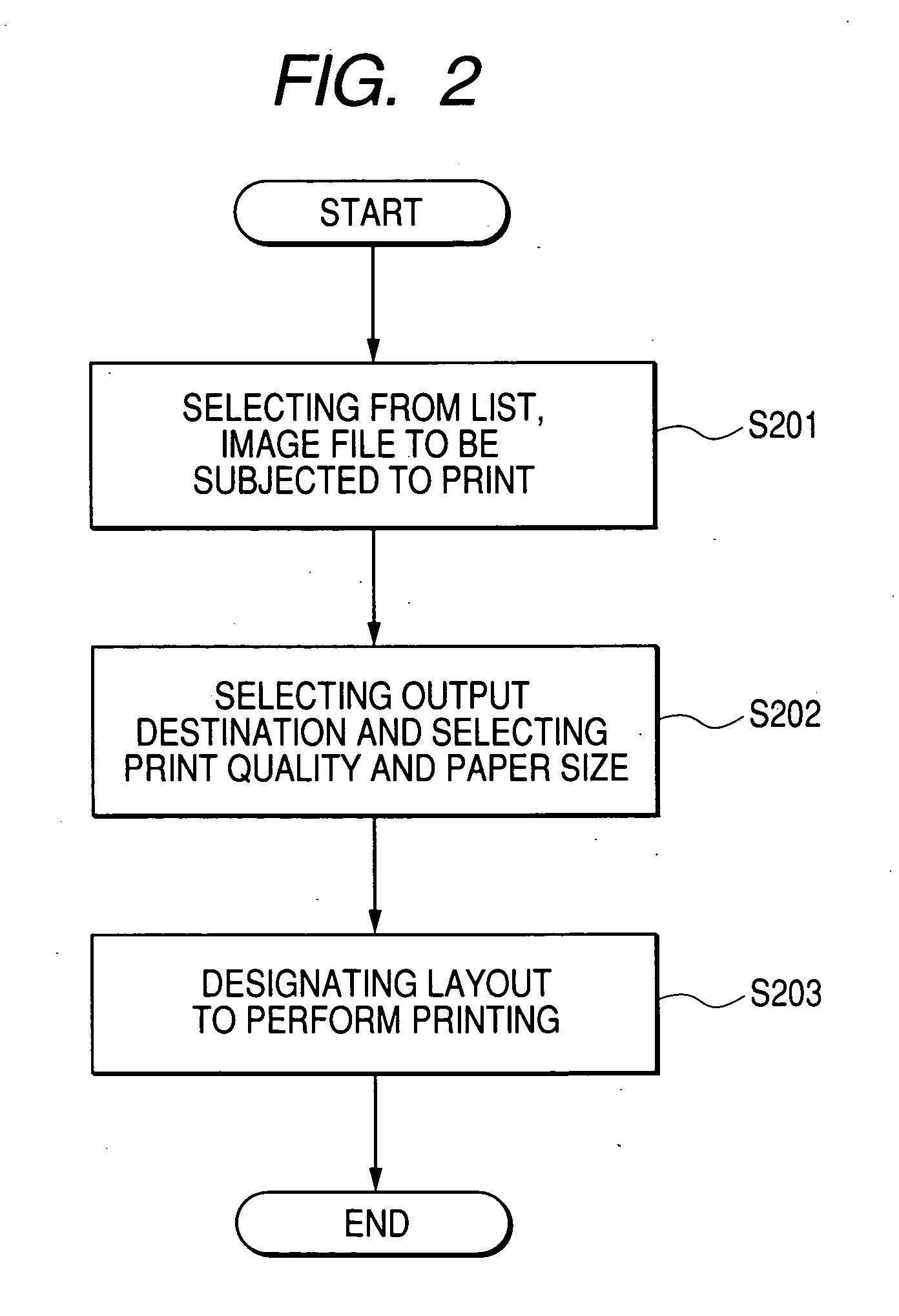
The printing apparatus of the first embodiment has the configuration in which the designation is performed in order of the image to be subjected to printing, the medium to be subjected to printing, and the layout. However, for the designation of the image to be subjected to printing and the designation of the medium to be subjected to printing, it is not necessary to fix the operation order. Further, for the designation of the layout, it is also possible that the operation order of these three functions is not fixed by adding the processing of the case of the non-designation. In addition to the configuration of the first embodiment, an example of GUI including the function of directly jumping to each step in the three steps will be described in a second embodiment.
FIG. 7 shows the general outline of the screen for designating the image to be subjected to printing in the second embodiment. A folder tree window 709 displays a tree indicating directories constructed in the storage me...
third embodiment
The method in which the optimum layout is determined to perform the printing while the preview is confirmed was described in the first embodiment. In this case, after the print instruction button 507 of FIG. 5 is depressed, the image file is decoded to start the printing processing. When the image size is larger, sometimes the processing time for actually starting the printing becomes longer and it is necessary that the user waits for a long time. Therefore, the method of shortening the time for starting the printing will be described in a third embodiment.
Because the third embodiment has the same system configuration as the first embodiment, the description of the system configuration will be neglected.
FIG. 14 is the flow chart for explaining the process of shortening the time for starting the printing. When the application is started up, the thumbnail of the image file is decoded to display the image designating screen of FIG. 3 in Step S1401. In Step S1402, the user selects N...
PUM
 Abstract
Description
Claims
Application Information
 - R&D
- Intellectual Property
- Life Sciences
- Materials
- Tech Scout
- Unparalleled Data Quality
- Higher Quality Content
- 60% Fewer Hallucinations
Browse by: Latest US Patents, China's latest patents, Technical Efficacy Thesaurus, Application Domain, Technology Topic, Popular Technical Reports.
© 2025 PatSnap. All rights reserved.Legal|Privacy policy|Modern Slavery Act Transparency Statement|Sitemap|About US| Contact US: help@patsnap.com


