Device having a pulsation reducing structure, a passage forming body and compressor

a technology of pulsation reducing structure and compressor, which is applied in the direction of positive displacement liquid engine, piston pump, liquid fuel engine, etc., can solve the problems of difficult to reduce the inner diameter of the cylindrical member to obtain and generate great pressure loss, etc., to suppress pressure loss, reduce structure, and achieve sufficient pulsation reducing

Inactive Publication Date: 2005-01-06
TOYOTA IND CORP
View PDF9 Cites 23 Cited by
  • Summary
  • Abstract
  • Description
  • Claims
  • Application Information

AI Technical Summary

Benefits of technology

[0005] Accordingly, it is an objective of the present invention to provide a device having a pulsation reducing structure that obtains sufficient pulsation reducing effect and suppresses pressure loss in devices having a gas passage. The present invention also pertains to a passage forming body and a compressor.

Problems solved by technology

However, if the inner diameter of the cylindrical member is excessively reduced, a great pressure loss is generated.
Therefore, it is difficult to reduce the inner diameter of the cylindrical member to obtain sufficient pulsation reducing effect.

Method used


Image

  • Device having a pulsation reducing structure, a passage forming body and compressor
  • Device having a pulsation reducing structure, a passage forming body and compressor
  • Device having a pulsation reducing structure, a passage forming body and compressor

Examples


first embodiment

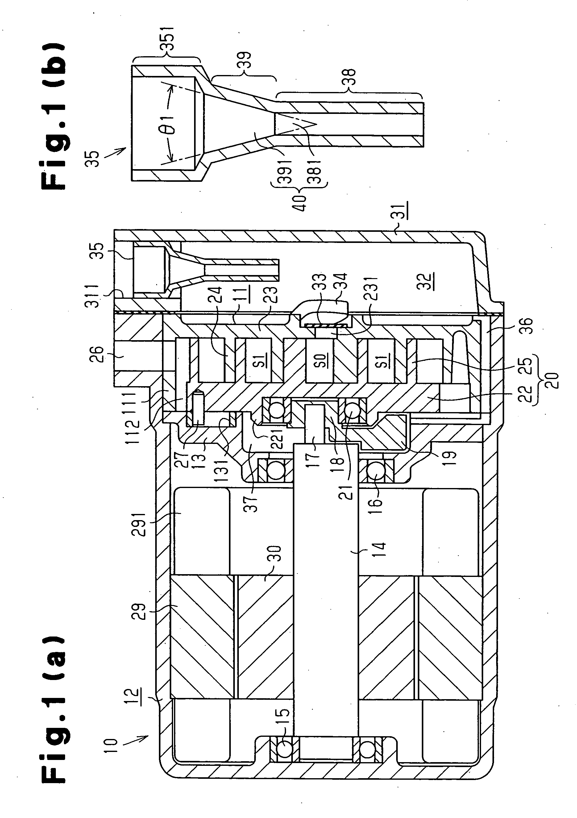
[0021] the present invention will now be described with reference to FIGS. 1(a) and 1(b).

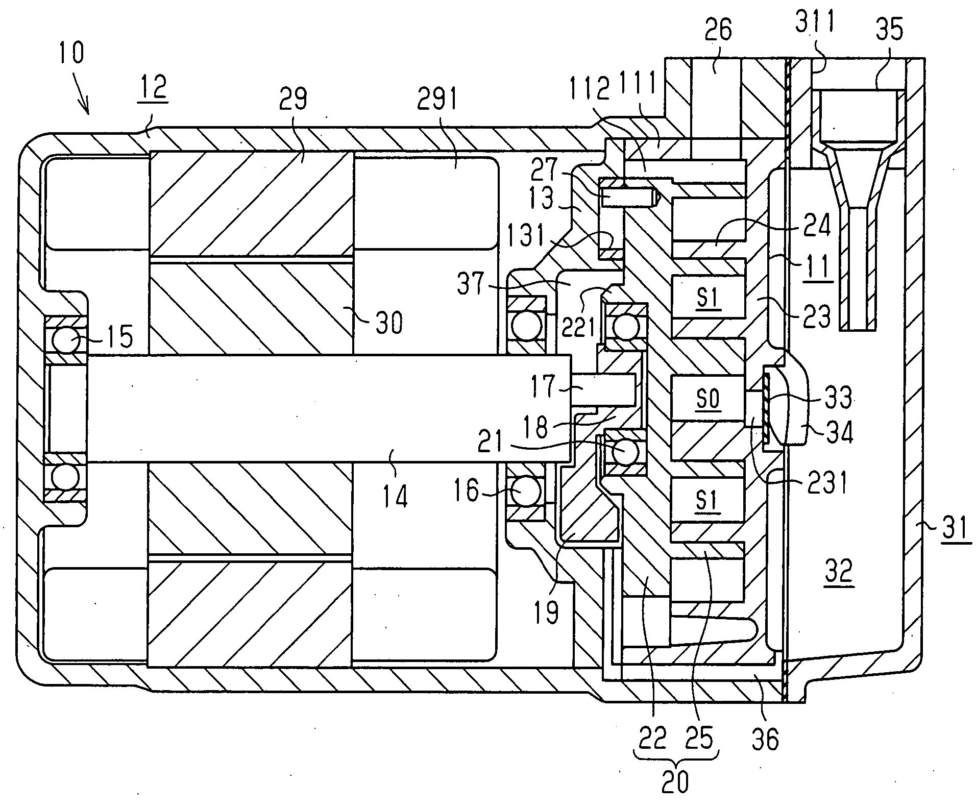
[0022] As shown in FIG. 1(a), a scroll compressor 10 includes a rear housing member 12 and a front housing member 31. A shaft support member 13 and a fixed scroll 11 are inserted in and fixed to the rear housing member 12. The front housing member 31 is secured to the rear housing member 12 and the fixed scroll 11. The rear housing member 12 and the front housing member 31 form a housing of a device, which is the scroll compressor 10. The rear housing member 12 and the shaft support member 13 rotatably support a rotary shaft 14 by means of radial bearings 15, 16.

[0023] The rotary shaft 14 extends through the shaft support member 13 and projects toward the fixed scroll 11. An eccentric shaft 17 is formed integrally with the end of the rotary shaft 14 that projects from the shaft support member 13. The axis of the eccentric shaft 17 located at a position decentered from the axis of the rotary sha...


PUM


Abstract

Pulsation of gas spreads from a pulsation source to a gas passage in a device. A muffler is located in a part of the gas passage. A combined passage is located upstream or downstream of the muffler with respect to a flowing direction of gas. The combined passage includes a restricting passage and a pressure restoring passage, which are connected in series. The pressure restoring passage is located downstream of the restricting passage with respect to the flowing direction of gas. The muffler is located between the pulsation source and the combined passage in the gas passage. Therefore, the device obtains sufficient pulsation reducing effect and suppresses pressure loss.

Description

BACKGROUND OF THE INVENTION [0001] The present invention relates to a device having a pulsation reducing structure. The present invention also pertains to a passage forming body and a compressor. [0002] In a scroll compressor disclosed in Japanese Laid-Open Patent Publication No. 2002-285981, an oil separator is located in a front housing member. An oil separating chamber, which forms part of the oil separator, is connected to a discharge chamber defined at the back of a fixed scroll. The oil separating chamber accommodates a cylindrical member, which forms part of the oil separator. Refrigerant gas in the discharge chamber is introduced into the oil separating chamber. Lubricant oil included in the refrigerant gas introduced into the oil separating chamber is separated from the refrigerant gas. [0003] The cylindrical member, which forms part of the oil separator, also functions to reduce pulsation of discharged gas. [0004] The inner diameter of the cylindrical member needs to be re...

Claims


Application Information

Patent Timeline
Patent Type & Authority Applications(United States)
IPC IPC(8): F04B27/08F04B27/10F04B39/00F04C29/06
CPCF04B27/1081F04C29/068F04B39/0055
Inventor KIMURA, KAZUYAKUROKI, KAZUHIROGENNAMI, HIROYUKISUITOU, KEN
Owner TOYOTA IND CORP
Why Eureka
Try Eureka