
Hermetic compressor

Inactive Publication Date: 2005-01-06
LG ELECTRONICS INC
View PDF3 Cites 7 Cited by
  • Summary
  • Abstract
  • Description
  • Claims
  • Application Information

AI Technical Summary

Benefits of technology

[0027] The lower frame which is combined on a lower surface of the cylinder so that it can be sealed includes a through hole through which the rotational shaft rotably passes at the center of the frame, a high pressure chamber for reducing noise generated in gas discharged while gas compressed in the compressing space of the compressing space of the cylinder in the circumferential direction is temporarily stored and discharged, and a discharge passage for connecting the high pressure chamber and compressing space.
[0031] The sealing plate is formed in a shape of a circular disk having a predetermined thickness, a through hole through which the rotational shaft passes is formed at the center of the sealing plate, and a sealing member for preventing gas from being leaked from the high pressure chamber is mounted in the inner and outer circumferential directions of the high pressure chamber.

Problems solved by technology

Therefore, the thickness of the case becomes thicker and manufacturing cost is increased by reinforcing the strength of the case.
Also, since the high temperature and high pressure gas passes between the stator and rotor of the driving unit, temperature of the driving unit increases and performance of the driving unit is degraded.
Also, since the high temperature and high pressure gas causes pressure loss by increased flow resistance of the gas and passes the inside of the case, noise was increased by pressure pulsation caused by difference of internal volume of the case.

Method used


Image

  • Hermetic compressor
  • Hermetic compressor
  • Hermetic compressor

Examples


Embodiment Construction

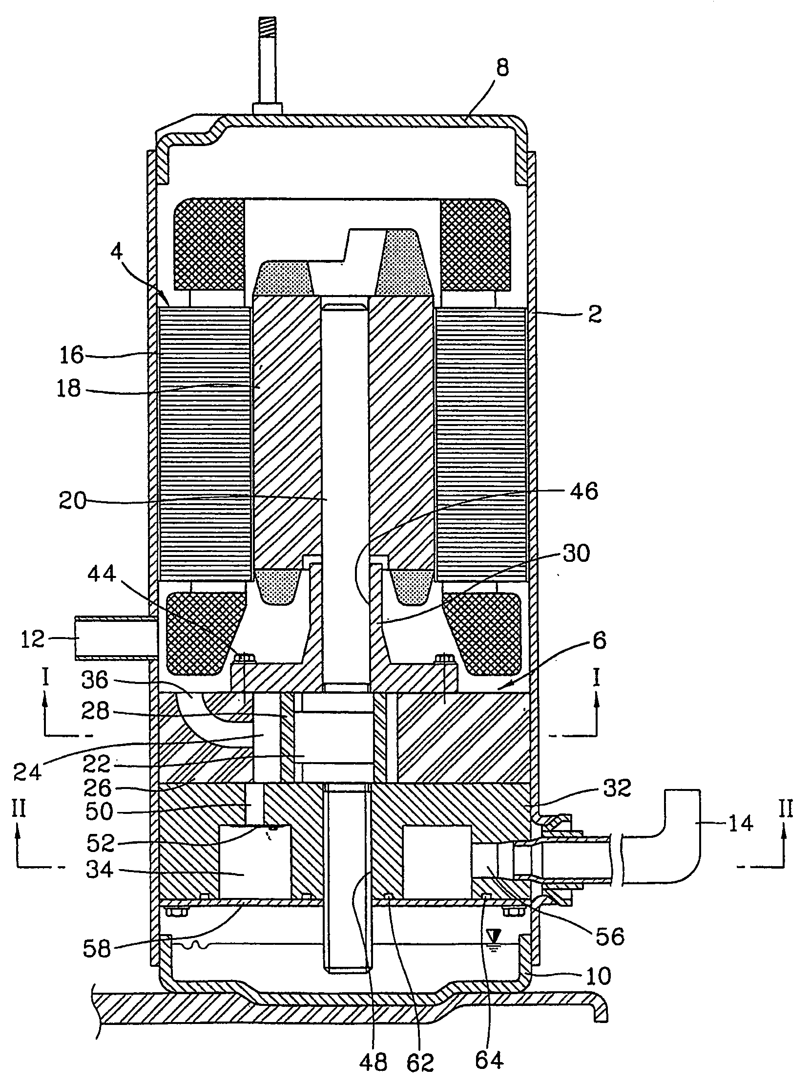
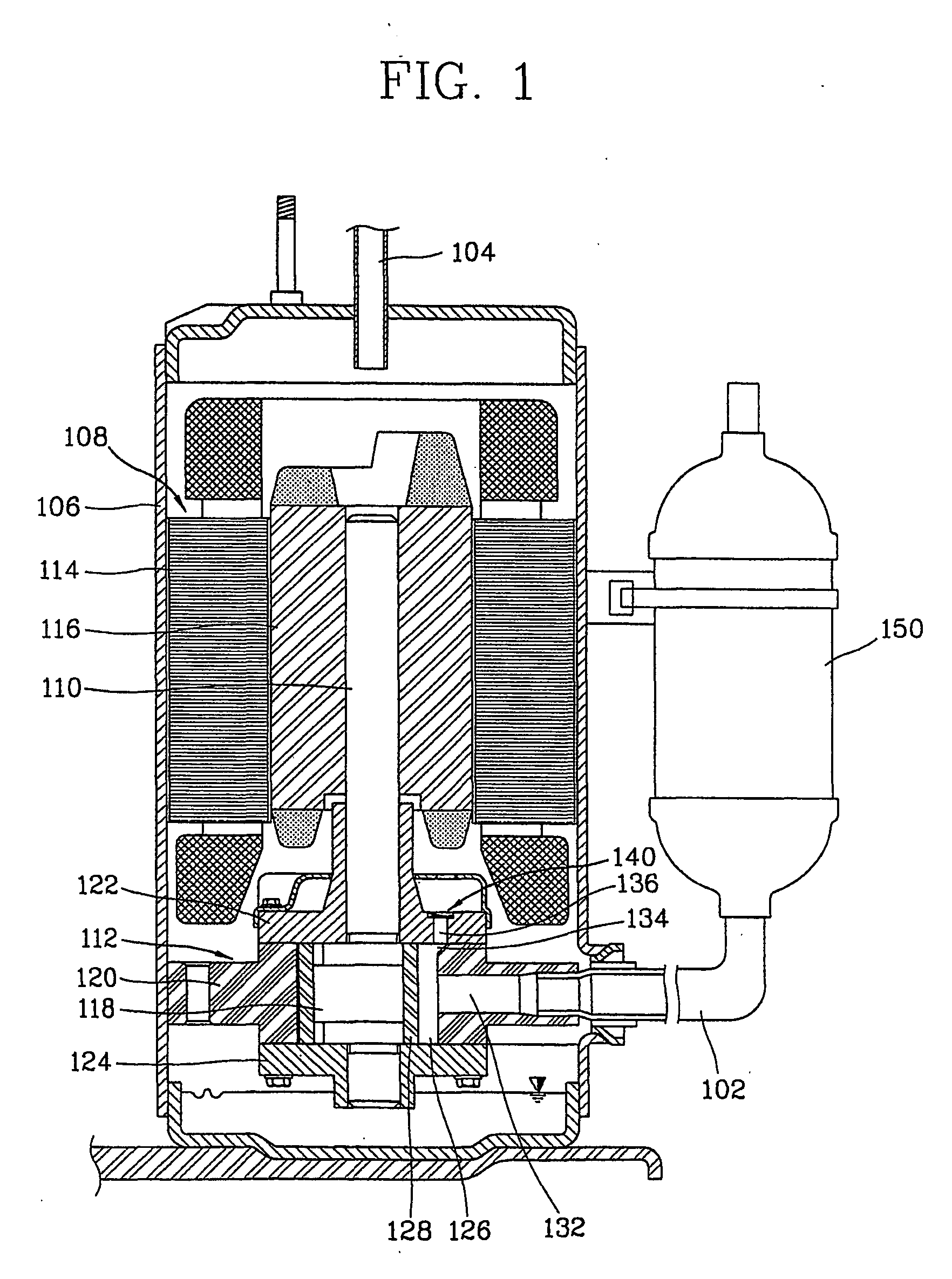
[0021] In order to achieve the above objects, there is provided a hermetic compressor, including a case having a hermetic space through which gas with low temperature and pressure being connected with a suction tube at a side and a discharge tube which is connected with the other side to discharge the compressed gas, a driving unit mounted at an upper side of the case, for generating a driving force and a compressing unit mounted at a lower side of the case and connected to the driving unit by a rotational shaft so as to compress the gas with low temperature and low pressure sucked into the case through the suction tube by a rotational force generated from the driving unit and discharge the gas through the discharge tube.

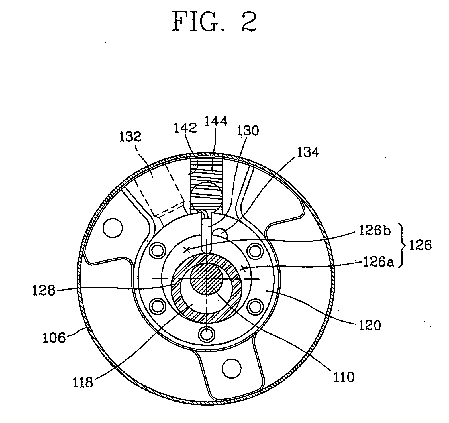
[0022] The compressing unit includes an eccentric ring which is fixed at a lower side of the rotational shaft, a cylinder in which the eccentric ring is rotably mounted, a compression space where gas is compressed is formed, a suction passage for guiding gas sucked...


PUM


Abstract

A hermetic compressor is disclosed to reduce a production cost, for which low temperature and low pressure gas passes inside a case to reduce a pressure inside the case so that it is not necessary to increase the thickness of the case and to reinforce a strength. The hermetic compressor includes a case having a suction tube and a discharge tube; a driving unit installed at an upper side of the case and generating a driving force; and a compressing unit installed at a lower side of the case and connected to the driving unit by a rotational shaft so as to compress the low temperature and low pressure gas sucked into the case through the suction tube by a rotational force generated from the driving unit and discharge the gas through the discharge tube.

Description

TECHNICAL FIELD [0001] The present invention relates to a hermetic compressor and particularly, to a hermetic compressor, capable of improving compression performance of gas and reducing noise. BACKGROUND ART [0002] Generally, a compressor can be formed by various types according to compressing methods, and as an air conditioning apparatus which is required to be smaller and lighter, a hermetic rotary compressor is mainly used. [0003]FIG. 1 is a transverse sectional view showing a hermetic compressor in accordance with the conventional art, and FIG. 2 is a longitudinal sectional view showing a compressing unit of the hermetic compressor in accordance with the conventional art. [0004] A hermetic rotary compressor in accordance with the conventional art includes a case 106 having a hermetic space therein, which is connected with a suction tube 102 to which gas is sucked and a discharge tube 104 through which compressed gas is discharged, a driving unit 108 which is mounted at an upper...

Claims


Application Information

Patent Timeline
IPC IPC(8): F04C18/356F04C23/00F04C29/12F04C29/00
CPCF04C23/008F04C18/3564F04C29/00
Inventor KIM, KWANG-HO
Owner LG ELECTRONICS INC
Learn More