Lever-type connector and connector housing therefor

a technology of lever-type connectors and connector housings, which is applied in the direction of coupling device connections, coupling parts engagement/disengagement, and incorrect coupling prevention, etc., can solve the problem of unnecessary additional resistance and achieve the effect of reducing operation resistan

Inactive Publication Date: 2005-01-06
SUMITOMO WIRING SYST LTD
View PDF7 Cites 3 Cited by
  • Summary
  • Abstract
  • Description
  • Claims
  • Application Information

AI Technical Summary

Benefits of technology

[0008] The invention relates to a lever-type connector with first and second housings that are connectable with each other. A lever is mounted rotatably on the first housing and is formed with a cam means. A mating cam means is provided on the second housing and is engageable with the cam means to display a cam action. The lever is positioned first at a connection starting position so that the cam means engages the mating cam means. An operable portion of the lever is moved away from center axes of the two housings along a connecting direction to an upright position and then is moved towards the center axes of the two housings along a connecting direction and towards an opposite side to bring the lever to a connection ending position for connecting the housings properly. A peak where a connection resistance between the housings and / or an operation resistance on the lever both are at their maximums is set to be reached while the lever is rotated from the upright position towards the connection ending position. Thus, the operation resistance is reduced when the lever is rotated beyond the peak.
[0009] The lever can be operated beyond the peak position and to the connection ending position at a single stroke by the pushing force exerted on the operable portion of the lever at the peak. The connection resistance between the housings and the operation resistance on the lever are at their maximums at or near the peak. Thus, resistance means for creating an additional inertial force is unnecessary and the maximum value of the operation resistance is lower in absolute value. Therefore, an operator is less likely to stop the connecting operation erroneously due to an increased operation resistance, and the housings can be connected properly with high reliability.

Problems solved by technology

Thus, it is unnecessary to provide additional resistance means to create an inertial force.

Method used


Image

  • Lever-type connector and connector housing therefor
  • Lever-type connector and connector housing therefor
  • Lever-type connector and connector housing therefor

Examples


Embodiment Construction

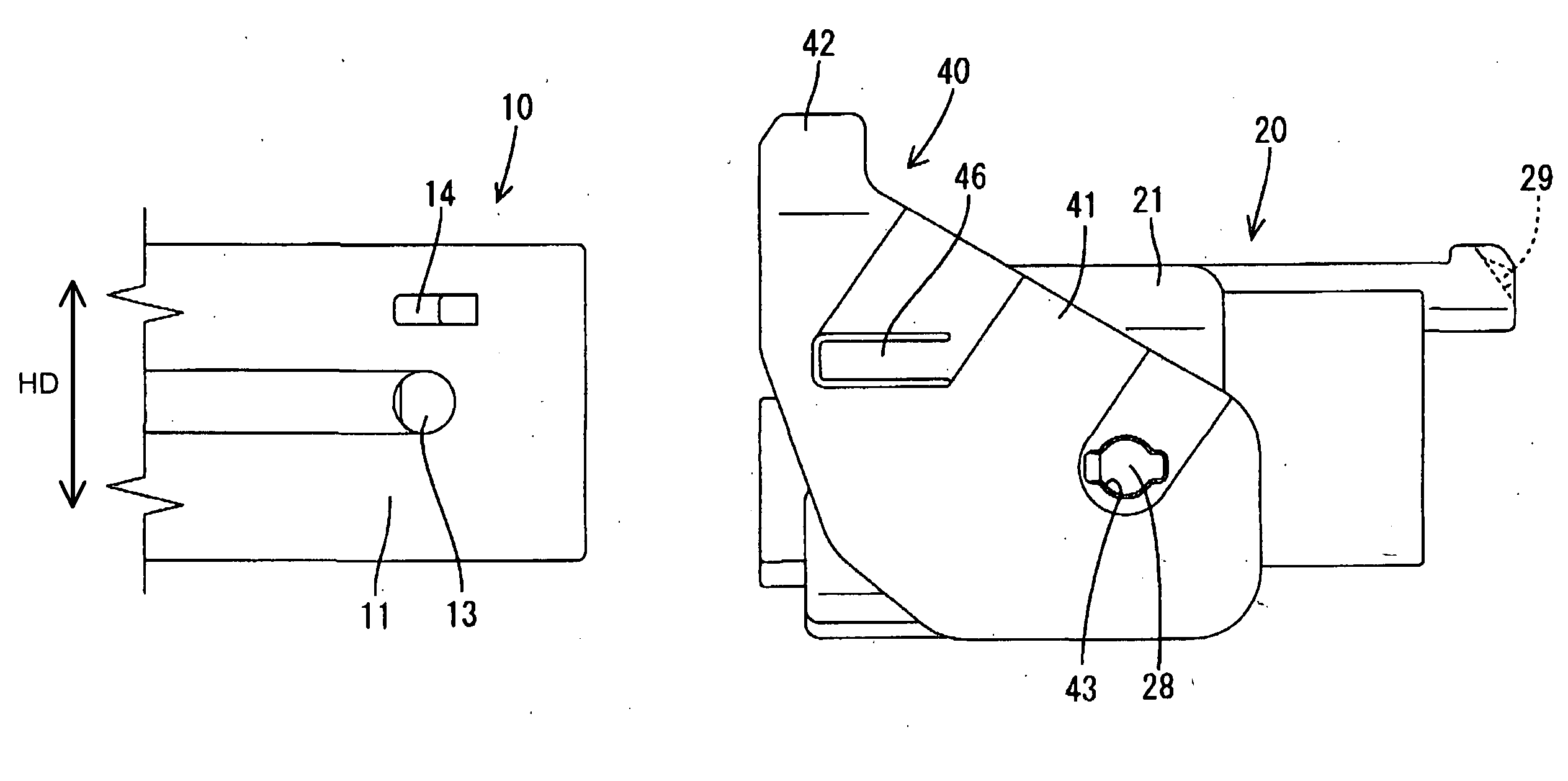
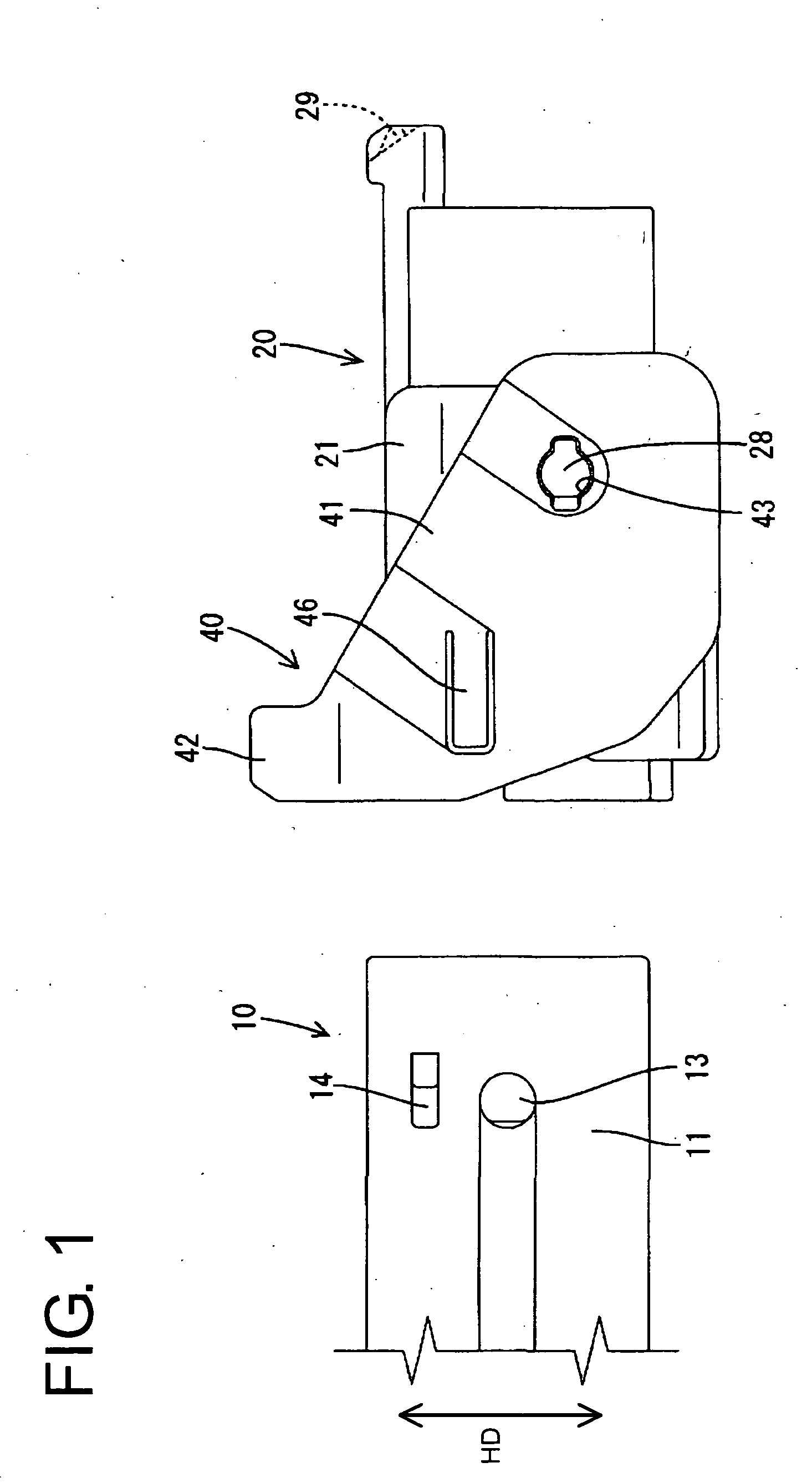
[0024] A lever-type connector according to the invention is illustrated in FIGS. 1 to 8 and includes a male housing 10, a female housing 20, and a lever 40 to be mounted on the female housing 20. In the following description, connecting sides of the housings 10, 20 are referred to as the front side.

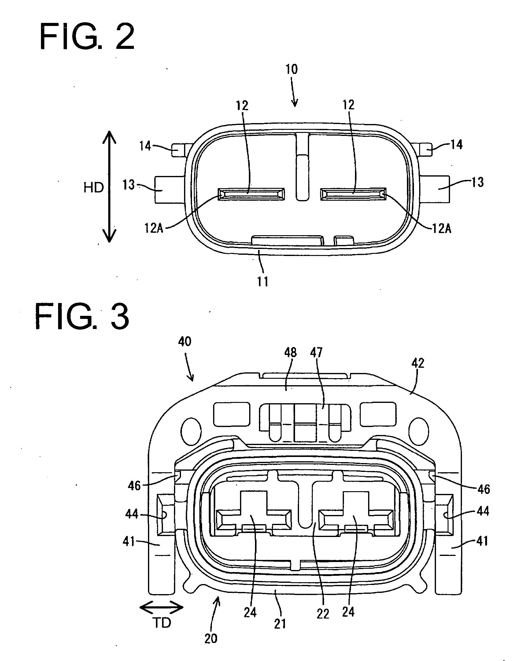
[0025] The male housing 10 is made e.g. of a synthetic resin, and is formed unitarily with an unillustrated device. A substantially rectangular tubular fitting 11 projects forward from the male housing 10, as shown in FIGS. 1 and 2. Two tabs 12 of male terminal fittings project substantially side by side from the back end wall of the tubular fitting 11. Each tab 12 is a substantially flat plate and has a tapered leading end 12A. A substantially cylindrical cam pin 13 projects from each of the left and right outer surfaces of the tubular fitting 11 at a position slightly toward the front end in the middle with respect to the height direction HD. An unlocking projection 14 projects above e...


PUM


Abstract

A lever-type connector has two housings (10, 20) and a lever (40) with a cam for facilitating the connection of the housings (10, 20). The connector is configured so that a connection resistance between the housings (10, 20) and an operation resistance on the lever (40) reach their maximums at substantially the same time. Thus, a separate resistance generator is unnecessary, and an operator is less likely to erroneously stop the connecting operation upon an increase in the operation resistance caused by a separate resistance generator. Accordingly, the two housings (10, 20) can be connected properly with high reliability.

Description

BACKGROUND OF THE INVENTION [0001] 1. Field of the Invention [0002] The invention relates to a lever-type connector and a housing therefor. [0003] 2. Description of the Related Art [0004] U.S. Pat. No. 5,476,390 discloses a lever-type connector with a female housing. A lever is mounted on the female housing and is formed with a cam groove. The cam groove is engageable with a cam pin on a mating male housing. The housings are positioned initially with the lever at a connection starting position and with the cam pin facing the entrance of the cam groove. The lever then is rotated so that the cam pin moves along the cam groove to pull the housings together. The connector relies on the leverage of the lever to connect the two housings with a small force. [0005] The above-described housings may be left partly connected if the rotation of the lever is stopped before the housings are connected properly. An inertial locking mechanism has been studied to prevent the housings from being left ...

Claims


Application Information

Patent Timeline
Patent Type & Authority Applications(United States)
IPC IPC(8): H01R13/642H01R13/52H01R13/629
CPCH01R13/62933H01R13/5219
Inventor FUKAMACHI, MAKOTO
Owner SUMITOMO WIRING SYST LTD
Why Eureka
Try Eureka