Speech compression and decompression apparatuses and methods providing scalable bandwidth structure

a bandwidth structure and compression apparatus technology, applied in the field of speech signal encoding and decoding, can solve the problems of speech quality degradation, inability to fix the amount of data transmitted over a packet-based communication channel, and inability to achieve speech quality degradation

Inactive Publication Date: 2005-01-06
SAMSUNG ELECTRONICS CO LTD
View PDF5 Cites 13 Cited by
  • Summary
  • Abstract
  • Description
  • Claims
  • Application Information

AI Technical Summary

Problems solved by technology

Thus, the existing PSTN-based communication cannot transmit a speech signal that falls outside the 4 kHz bandwidth, resulting in degradation of speech quality.
However, the amount of data transmitted over a packet-based communication channel is not fixed, but varies due to a variety of factors.
As a result, the wideband communication channel necessary for the wideband speech encoder may not be secured, resulting in degradation of the speech quality.
This is because, if the required bandwidth is not provided at a specific moment, transmitted speech packets are lost and the speech quality is sharply degraded.
However, the encoding technique proposed in the ITU G.722 standard has the disadvantage that it is incompatible with existing standard narrowband compressors and has a high transmission rate.
However, the ITU G.722.1 standard has the disadvantage that it does not encode a speech packet into the scalable bandwidth structure and is incompatible with the existing standard narrowband compressor.
However, since theses speech encoding techniques just divide an input signal into two bands and process each band separately, a high-band signal processing unit cannot additionally process distortion caused by the narrowband speech compressor.
Also, when the high-band signal is compressed, acoustic characteristics of a speech signal are not used efficiently, resulting in a decrease in quantization efficiency.

Method used


Image

  • Speech compression and decompression apparatuses and methods providing scalable bandwidth structure
  • Speech compression and decompression apparatuses and methods providing scalable bandwidth structure
  • Speech compression and decompression apparatuses and methods providing scalable bandwidth structure

Examples


Embodiment Construction

Reference will now be made in detail to embodiments of the present invention, examples of which are illustrated in the accompanying drawings, wherein like reference numerals refer to the like elements throughout. The embodiments are described below in order to explain the present invention by referring to the figures.

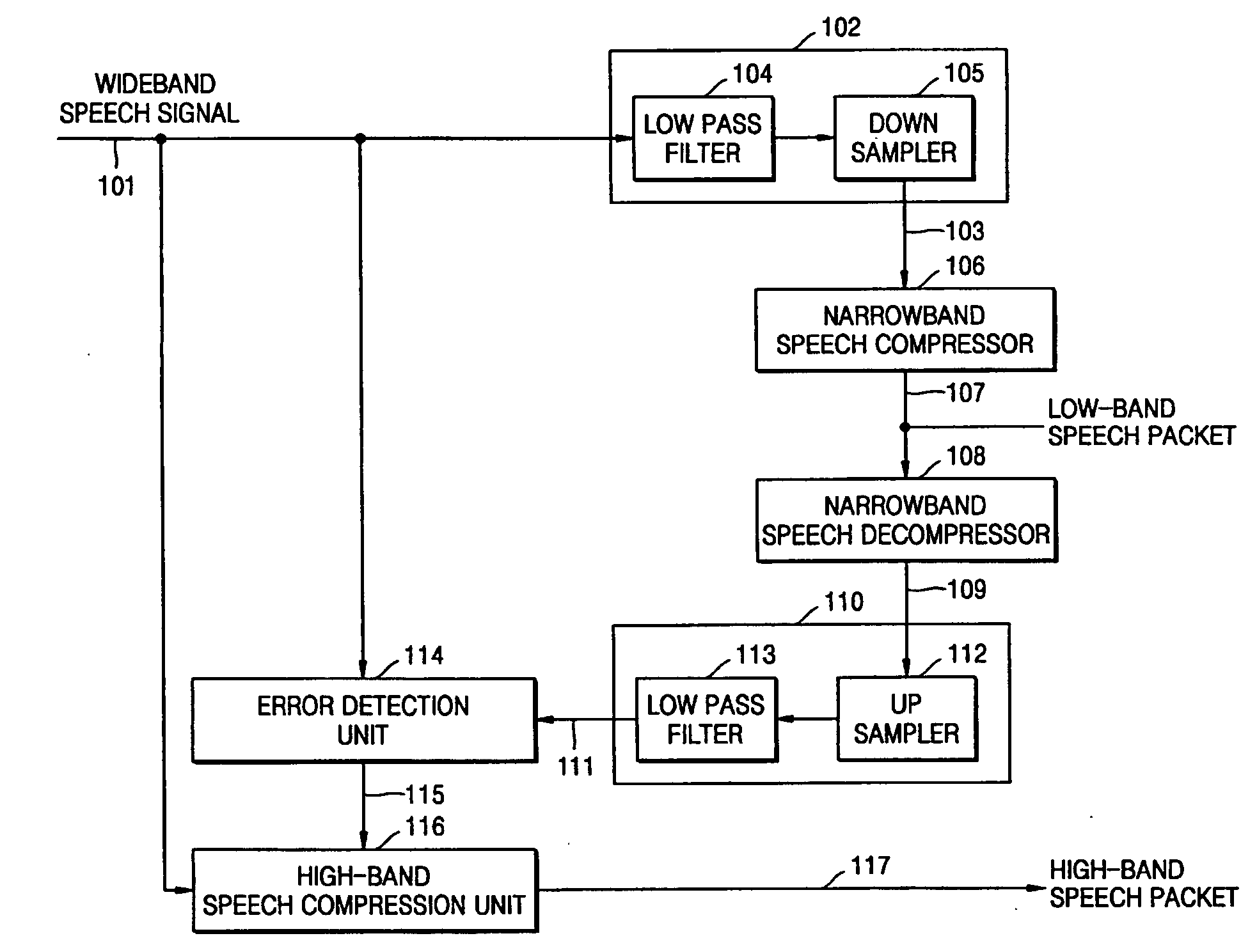
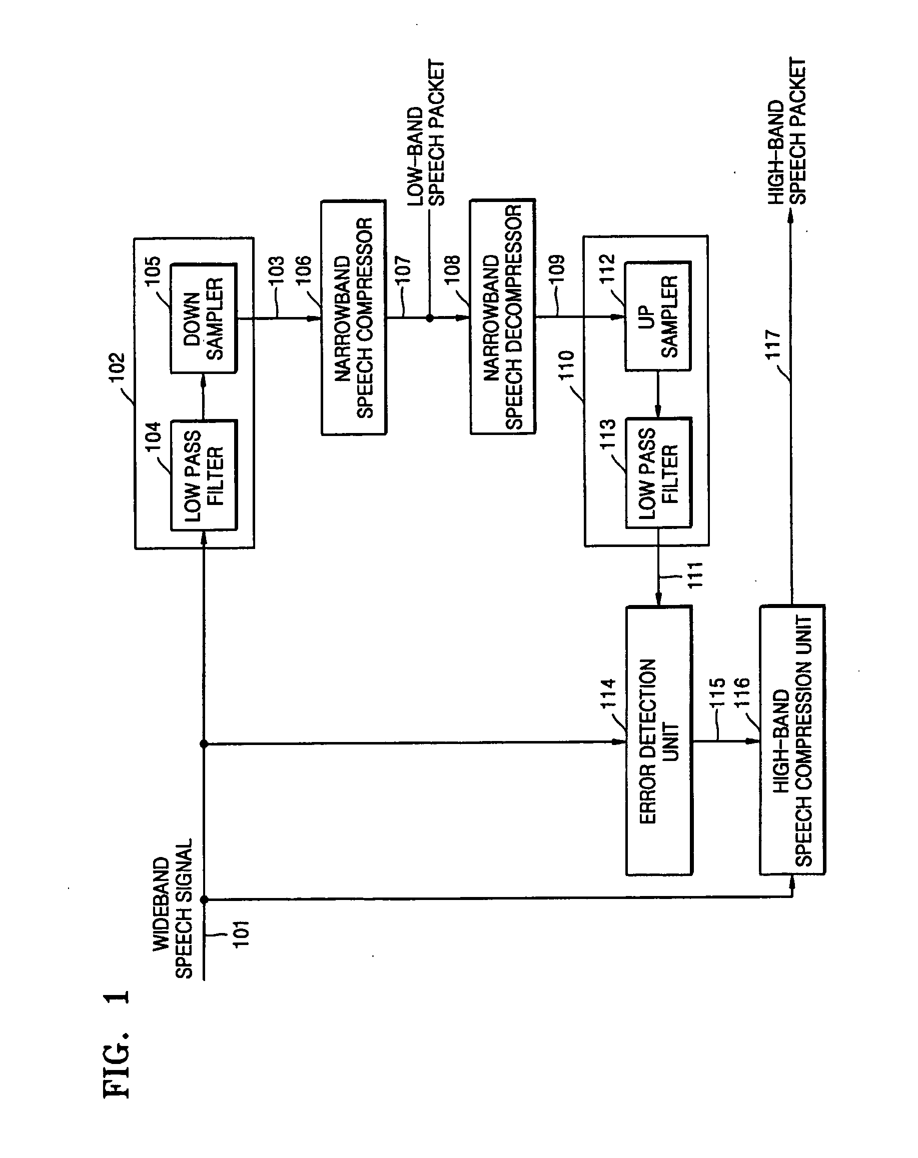
FIG. 1 is a block diagram of a speech compression apparatus according to an embodiment of the present invention. Referring to FIG. 1, the speech compression apparatus includes a first band-transform unit 102, a narrowband speech compressor 106, a narrowband speech decompressor 108, a second band-transform unit 110, an error detection unit 114, and a high-band speech compression unit 116.

The first band-transform unit 102 transforms a wideband speech signal input via a line 101 into a narrowband speech signal. The wideband speech signal is obtained by sampling an analog signal at 16 kHz and quantizing each sample by 16-bit pulse code modulation (PCM).

The first band-...


PUM


Abstract

A speech compression apparatus including: a first band-transform unit transforming a wideband speech signal to a narrowband low-band speech signal; a narrowband speech compressor compressing the narrowband low-band speech signal and outputting a result of the compressing as a low-band speech packet; a decompression unit decompressing the low-band speech packet and obtaining a decompressed wideband low-band speech signal; an error detection unit detecting an error signal that corresponds to a difference between the wideband speech signal and the decompressed wideband low-band speech signal; and a high-band speech compression unit compressing the error signal and a high-band speech signal of the wideband speech signal and outputting the result of the compressing as a high-band speech packet.

Description

CROSS-REFERENCE TO RELATED APPLICATION This application claims the priority of Korean Patent Application No. 2003-44842, filed on Jul. 3, 2003, in the Korean Intellectual Property Office, the disclosure of which is incorporated herein by reference. BACKGROUND OF THE INVENTION 1. Field of the Invention The present invention relates to speech signal encoding and decoding, and more particularly, to speech compression and decompression apparatuses and methods, by which a speech signal is compressed into a scalable bandwidth structure and the compressed speech signal is decompressed into the original speech signal. 2. Description of the Related Art With the development of communication technology, speech quality has emerged as a significant competitive factor among communication companies. Existing public switched telephone network (PSTN)-based communication samples a speech signal at 8 kHz and transmits a speech signal with a bandwidth of 4 kHz. Thus, the existing PSTN-based commu...

Claims


Application Information

Patent Timeline
Patent Type & Authority Applications(United States)
IPC IPC(8): G10L19/14G10L19/00H03M7/30
CPCG10L19/24G10L19/005G10L19/02
Inventor SON, CHANG-YONGPARK, HO-CHONGLEE, YONG-BEOMLEE, WOO-SUK
Owner SAMSUNG ELECTRONICS CO LTD
Why Eureka
Try Eureka