

Method of manufacturing spring assembly
- Summary
- Abstract
- Description
- Claims
- Application Information
AI Technical Summary
Benefits of technology
Problems solved by technology
Method used
Image

Examples
first embodiment
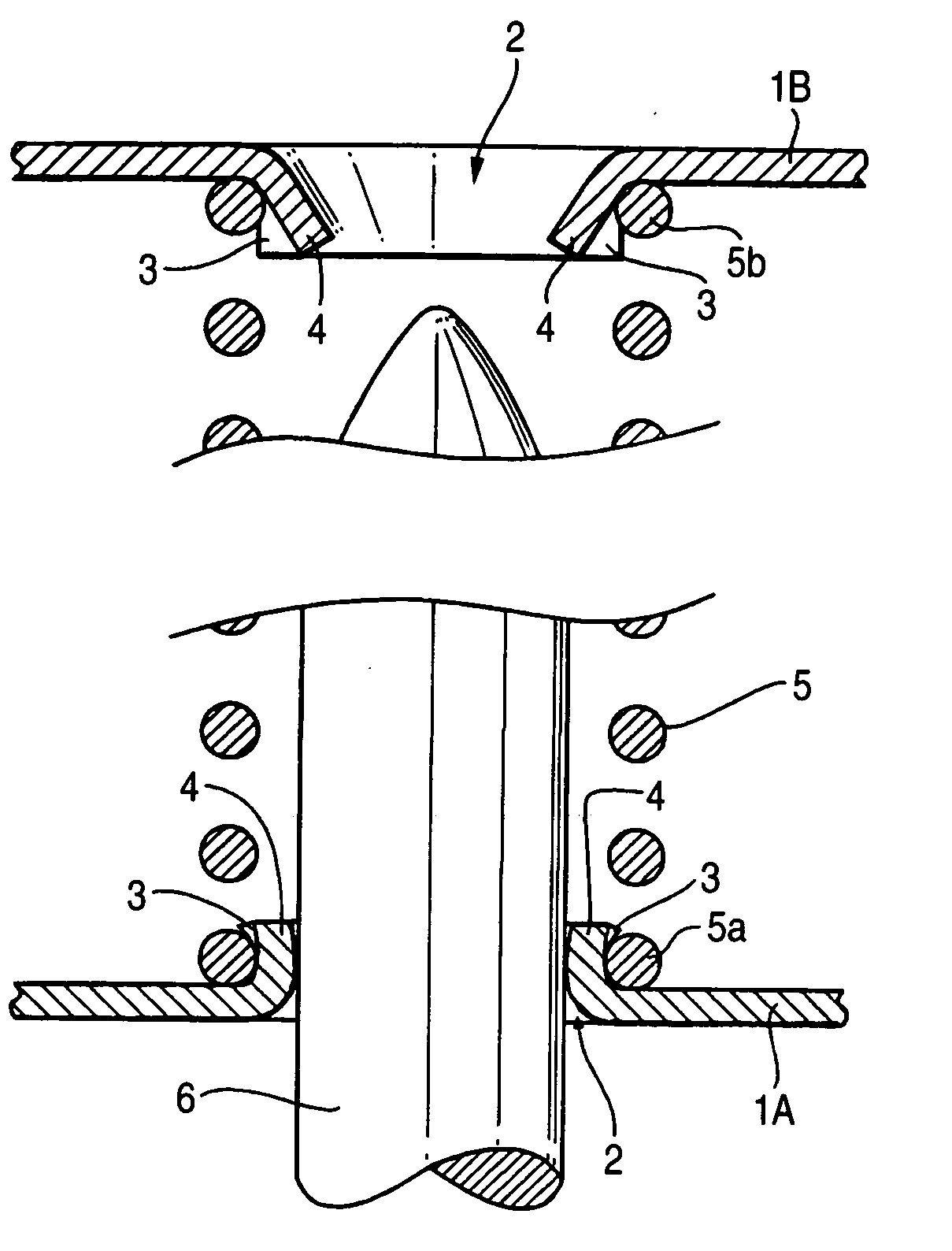
[0029] Hereinafter, the invention is described in detail on the basis of preferred embodiments thereof illustrated in the accompanying drawings. Basically, a method of manufacturing a spring assembly, which includes two annular plates, and plural compression coil springs, which are arranged in the circumferential direction of each of these annular plates and interposed therebetween, similarly to the spring assembly manufactured by the related method. It is assumed that each of both end turn portions of the compression coil springs is surrounded between the outer peripheral surface of the projection portion and the inner surface of the annular plate by outwardly enlarging each of the projection portions formed in each of the two annular plates. However, this embodiment of the invention features the following respects.
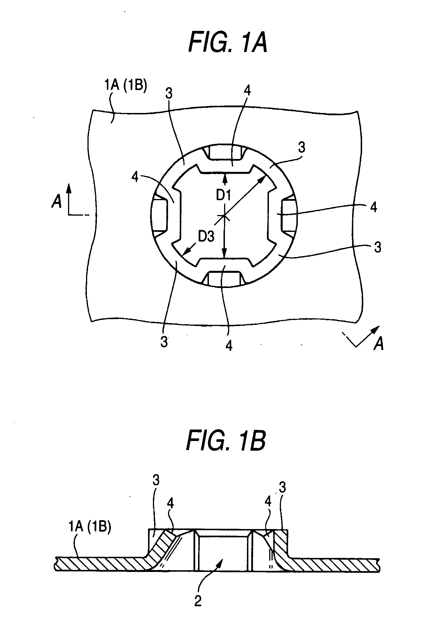
[0030] That is, first, regarding the two annular plates 1A and 1B, as shown in FIGS. 1A and 1B, cylindrical projection portions 2, which are formed in the inner surface...
second embodiment
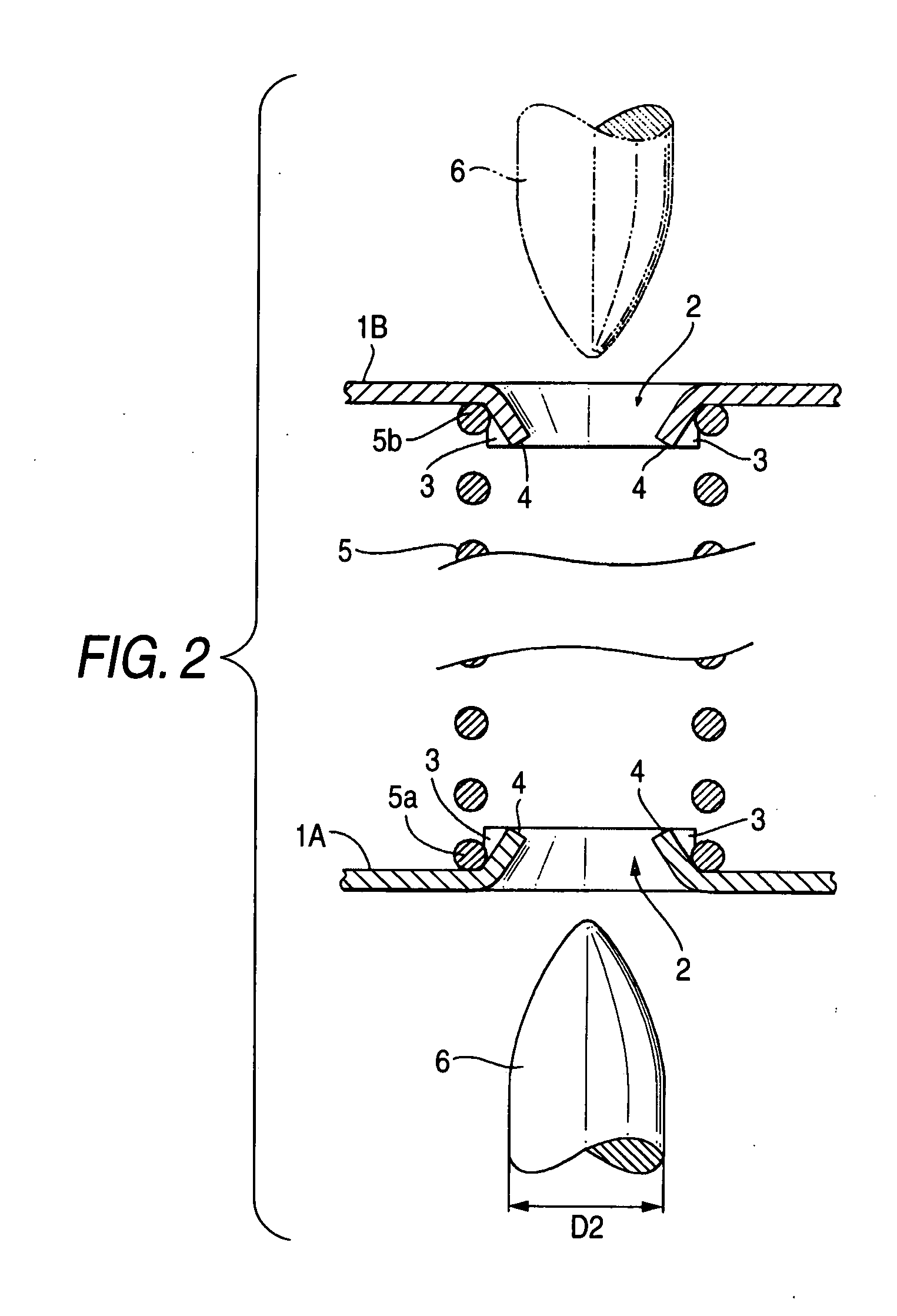
[0037] Incidentally, also, in the second embodiment, the two annular plates 1A and 1B having the same shape are used so as to share the annular plates 1A and 1B and the punch 6. However, even in this case, the spring assembly may be configured so that only simply cylindrical projection portions similar to the projection portions are formed in the other annular plate 1B, and that another punch having a portion, whose diameter is larger than the inside diameter of each of the projection portions, is inserted into the inside of these cylindrical projection portions to thereby enlarge the cylindrical projection portions. Thus, the other end turn portion 5b of the other compression coil spring 5 can be supported by being surrounded between the outer peripheral surface of the associated projection portion and the inner surface of the other annular plate 1B.
[0038] Finally, a method of manufacturing a spring assembly according to a third embodiment of the invention is described hereinbelow....
third embodiment
[0039] Thus, as shown in FIGS. 9A and 9B, first, simply cylindrical projection portions 2A, which are similar to those used by the related method, are formed in the other annular plate 1B. Then, a state, in which the other end turn portion 5b of each of the compression coil spring 5 is set on the outer periphery of each of the projection portions 2A, is obtained. Then, a punch 7 having a portion, whose diameter D5 is larger than the inside diameter D4 of the simply cylindrical projection portion 2A, is inserted thereinto, and the projection portion 2A is enlarged in diameter. Thus, the other end turn portion 5b of each of the compression coil spring 5 is supported by being surrounded between the outer peripheral surface of the simply cylindrical projection portion 2 and the inner surface of the other annular plate 1B. Thereafter, a state, in which one of the end turn portions 5a of the compression coil spring 5 is set on the outer periphery of each of the projection portions 2, in ...
PUM
| Property | Measurement | Unit |
|---|---|---|
| Diameter | aaaaa | aaaaa |
Abstract
Description
Claims
Application Information