Pressure control system

Active Publication Date: 2017-11-16
AIROPACK TECH GRP
View PDF7 Cites 3 Cited by
  • Summary
  • Abstract
  • Description
  • Claims
  • Application Information

AI Technical Summary

Benefits of technology

[0010]The present invention has the main advantage, that the vessel is spherical which can withstand larger forces so that the diameter of the high-pressure vessel can be enlarged with less

Problems solved by technology

If the vessel has to be enlarged, forces on the bottom plate will become m

Method used


Image

  • Pressure control system
  • Pressure control system
  • Pressure control system

Examples


Example

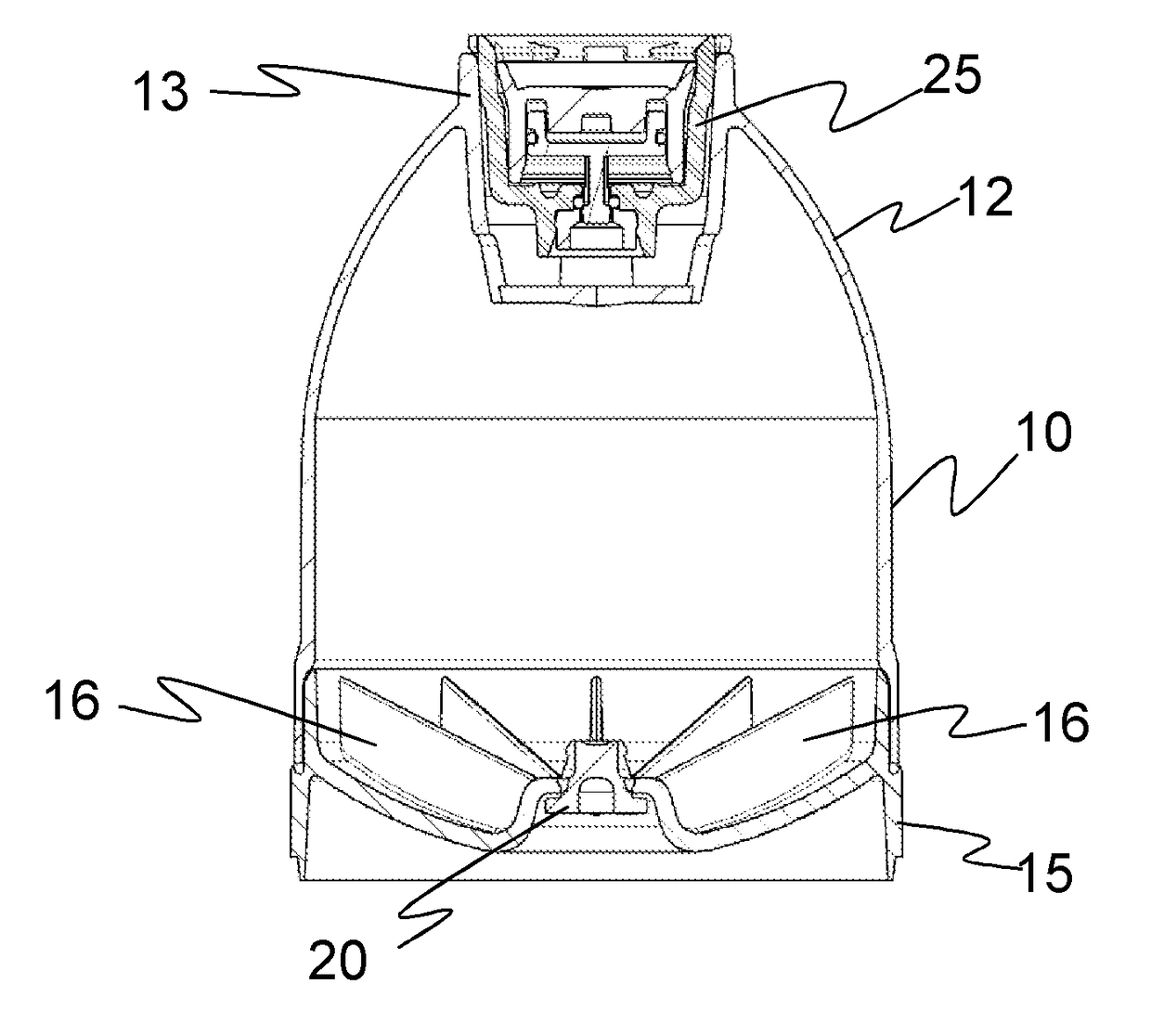
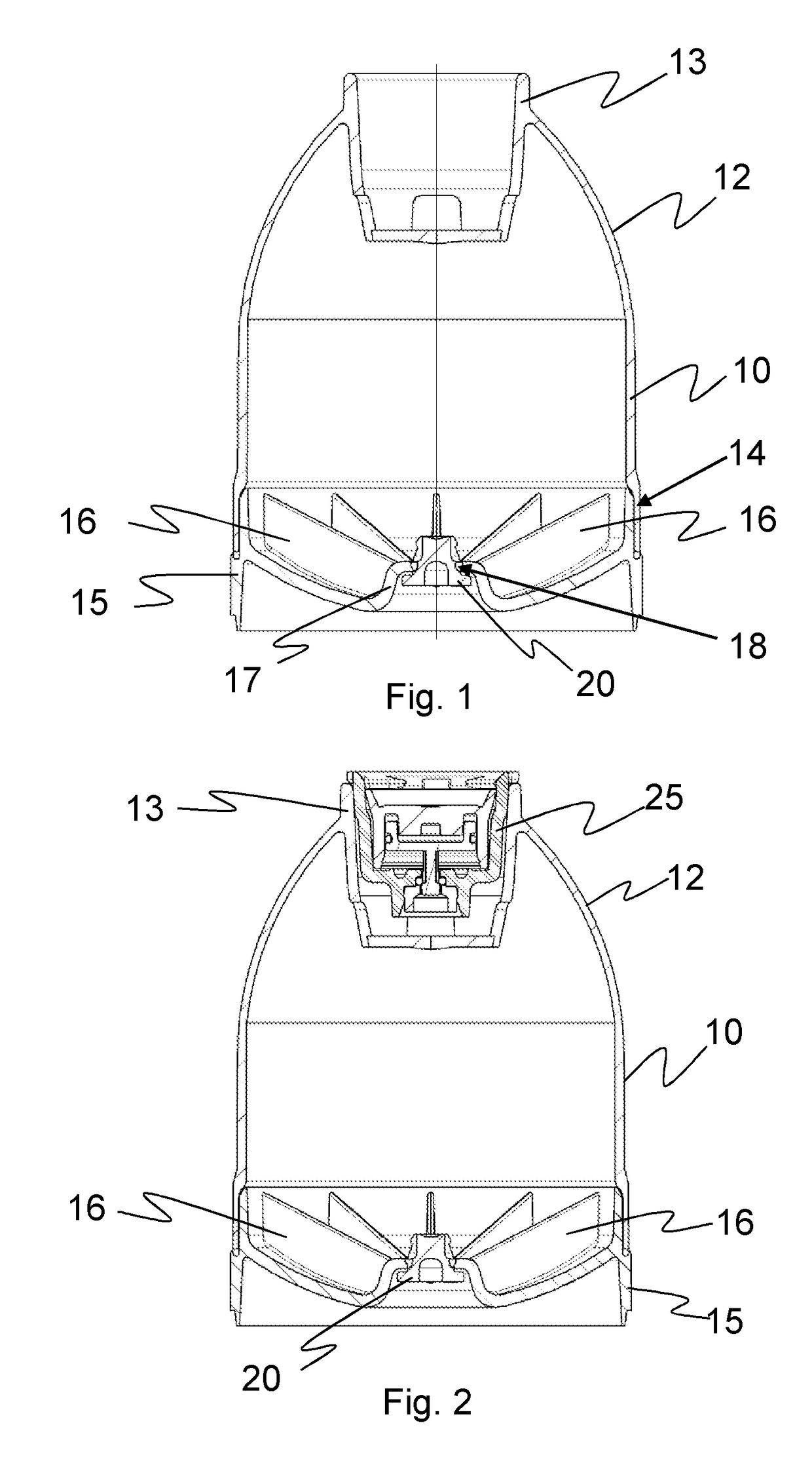
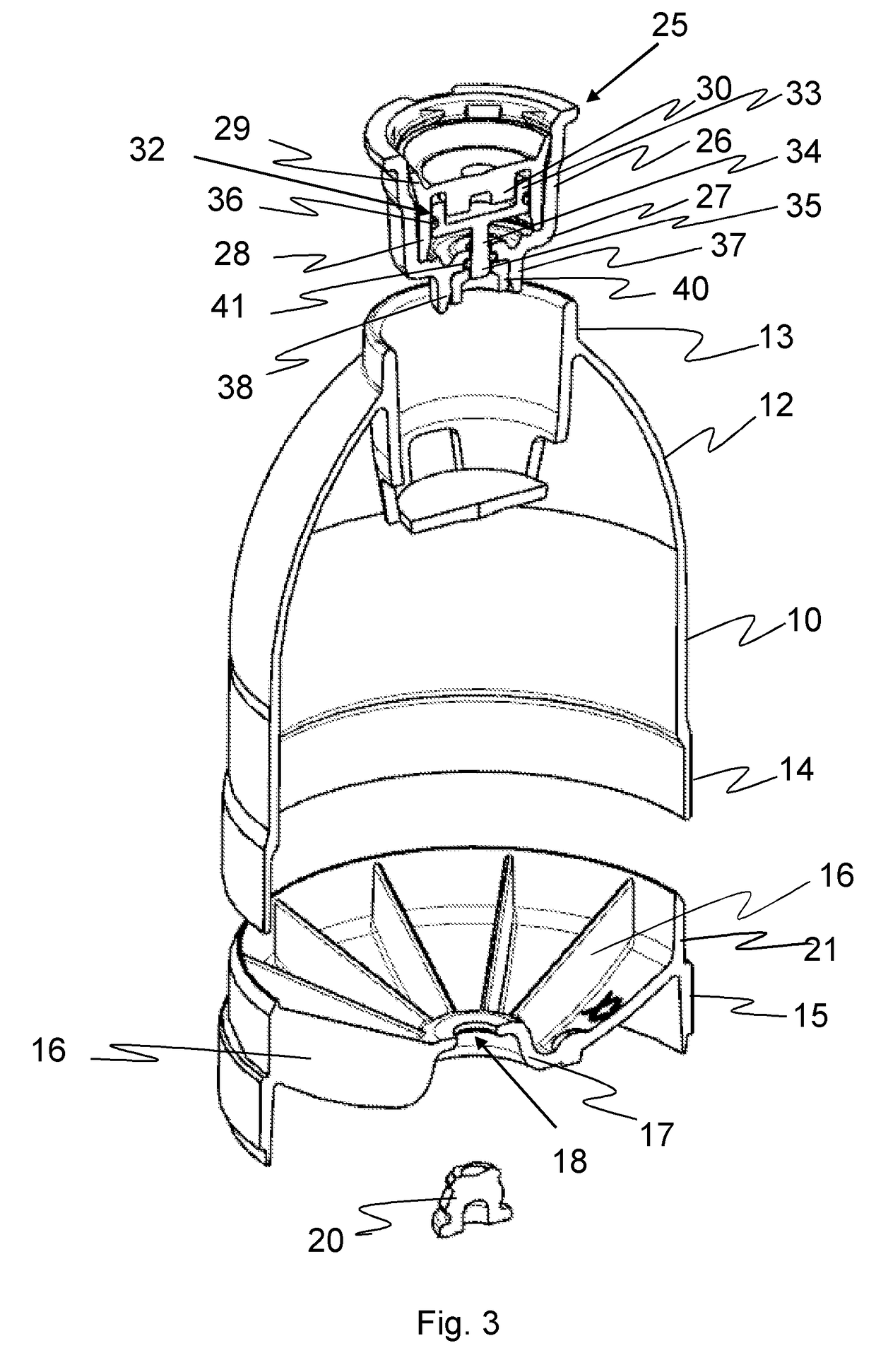
[0021]In FIG. 1 a high-pressure plastic vessel 10 is depicted, which is substantially cylindrical and has in the upper part a spherical dome 12 with a cylindrical insert 13.

[0022]The vessel 10 with the dome 12 and the insert 13 is made of one piece from a suitable plastic material as PET by injection moulding. The lower end 14 of the vessel 10 is open and is closed by a ring-shaped closure 15, which has internal reinforcing fins 16, which are uniformly distributed over the surface of the closure 15. In the closure 15 a reinforced retracted ring 17 with a central bore 18 is provided, in which a Nicholson plug 20 is clamped. The closure 15 is connected to the vessel 105 by laser welding.

[0023]The advantage of injection moulding of the high-pressure vessel10 is that the vessel 15 has its final form and does not have to cut as in the injection stretch blow moulding process previously mentioned. The melt polymer will be injected centrally in order to obtain a uniform material distributio...


PUM

PropertyMeasurementUnit
Pressureaaaaaaaaaa

Abstract

A novel pressure control system provided for maintaining a constant predetermined excess pressure in a fluid dispensing container comprises a high-pressure plastic vessel having an inner chamber and an upper open end, and a pressure control device with a valve, which pressure control device is mounted on the upper open end of the high-pressure vessel, whereas a passageway is provided from the inner chamber to the outside, which is controlled by the valve, wherein the vessel is substantially cylindrical.
The upper part of the vessel has a spherical dome with a cylindrical insert provided for receiving the pressure control device and the lower end of the vessel has an open end, which is closed by a ring-shaped closure.

Description

CROSS-REFERENCE TO RELATED APPLICATIONS[0001]This application is a National Stage application of International Patent Application No. PCT / EP2016 / 051837, filed on Jan. 28, 2016, which claims priority to European Patent Application No. EP15152846.0, filed on Jan. 28, 2015, each of which is hereby incorporated by reference in its entirety.TECHNICAL FIELD[0002]The invention pertains to a pressure control system provided for maintaining a constant predetermined excess pressure in a fluid dispensing container, comprising a high-pressure plastic vessel having an inner chamber and a closed end and an open end, and a pressure control device with a valve, which pressure control device is mounted on the open end of the high-pressure vessel, whereas a passageway is provided from the inner chamber to the outside, which is controlled by the valve.BACKGROUND OF THE INVENTION[0003]Such a pressure control system is described in WO-A-2005 / 082744, wherein the high-pressure vessel is substantially cyli...

Claims


Application Information

Patent Timeline
IPC IPC(8): B65D83/38B65D83/64B29C65/00B65D83/66B29C65/16
CPCB65D83/38B65D83/663B65D83/64B29C65/1635B29C66/5452B29C45/14
Inventor BROUWER, MARKDIERICKX, WILLIAMANTHIERENS, TOM
Owner AIROPACK TECH GRP
Why Eureka
Try Eureka