
Digital measurement system

a digital measurement and measurement system technology, applied in the direction of mechanical measuring arrangements, instruments, flat surface machines, etc., can solve the problems of inaccurate calibration, virtually impossible to properly calibrate the machine, and difficult to accurately calibrate the machine, etc., to achieve high accuracy and calibrated measurements

Active Publication Date: 2005-01-13
WIXEY BARRY
View PDF10 Cites 27 Cited by
  • Summary
  • Abstract
  • Description
  • Claims
  • Application Information

AI Technical Summary

Benefits of technology

[0006] It is therefore an object of the present invention to provide a digital measurement system that enables highly accurate, calibrated measurements to be taken and displayed conveniently in a wide variety of machines, tools and other applications.
[0007] It is the further object of this invention to provide a digital measurement system, which is extremely quick and easy to calibrate and which is far less tedious and time consuming, and much more efficient to calibrate than conventional digital measurement devices.
[0008] It is the further object of this invention to provide a digital measurement system that is particularly convenient for use in woodworking machines such as height-adjustable planers and sanders, and which enables such machines to be quickly and conveniently calibrated without first having to measure a standard board with calibers.
[0011] It is the further object of this invention to provide a digital readout with a fractional measurement display that is much more accurate than conventional fractional displays.
[0012] It is the further object of the present invention to provide a calibrated digital measuring system that maintains proper calibration over numerous uses and even after the readout has been turned off and on repeatedly.
[0013] This invention results from the realization that an electronic digital readout of the type utilized with woodworking machines and similar tools can be calibrated much more easily and efficiently by mounting the readout slidably on a reference scale that is itself mounted to be longitudinally adjustable on the machine. A calibrating reference board simply is placed between a lower end of the reference scale and a supporting table of the machine. The readout may then be quickly and accurately calibrated so that consistent, accurate measurements are thereafter obtained by the readout on the machine.

Problems solved by technology

Properly calibrating the readout device tends to be problematic.
As a result, it is virtually impossible to properly calibrate the machine by simply adjusting the height of the head alone.
This procedure requires extra, independent measurements and is tedious, time-consuming and subject to caliper misreadings and, as a result, inaccurate calibration results.
Moreover, readouts capable of such data entry are fairly complex and expansive instruments.
As a result, the user is unable to obtain the most accurate measurements possible.
This can result in measurements that are imprecise and unsatisfactory.
Moreover, conventional digital readouts do not provide an accurate and reliable, yet east to read and understand correlation between corresponding decimal and fractional equivalents.

Method used


Image

  • Digital measurement system
  • Digital measurement system
  • Digital measurement system

Examples


Embodiment Construction

[0020] Other objects, features and advantages will occur from the following description of preferred embodiments and the accompanying drawings, in which:

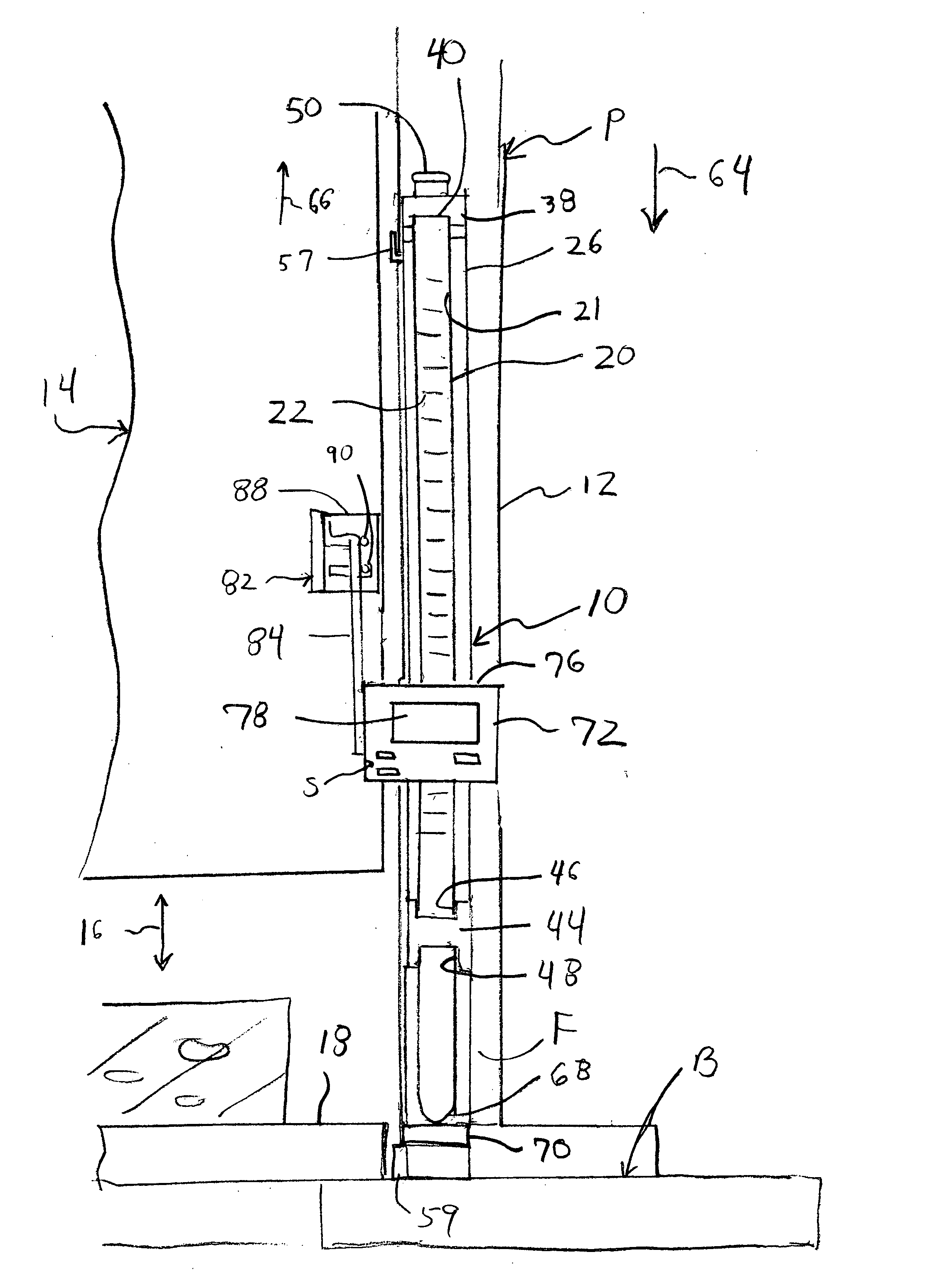
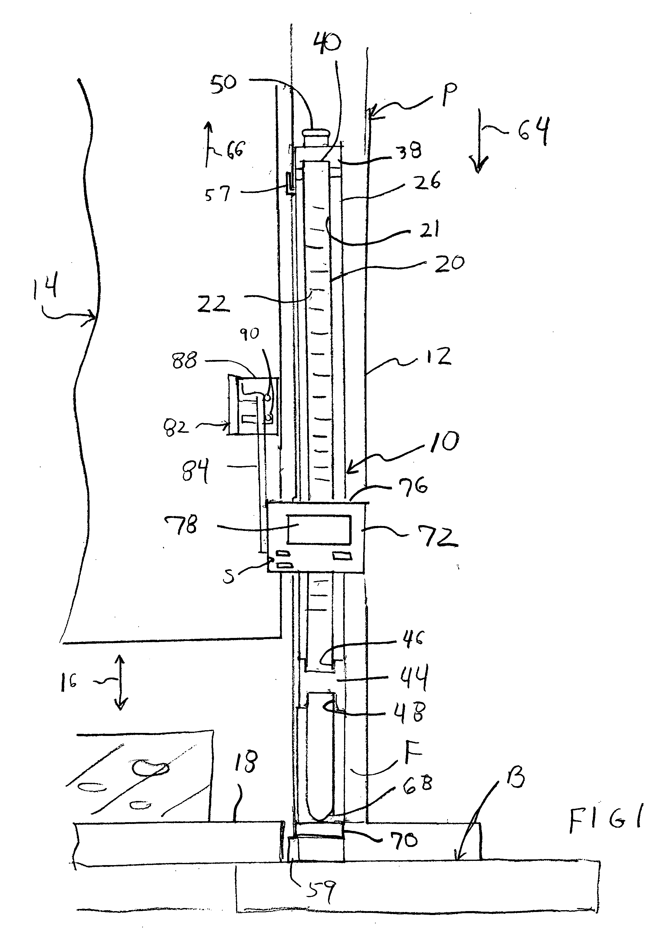
[0021]FIG. 1 is a front elevational view of a representative woodworking machine, namely a planer, employing the digital measurement system of this invention;

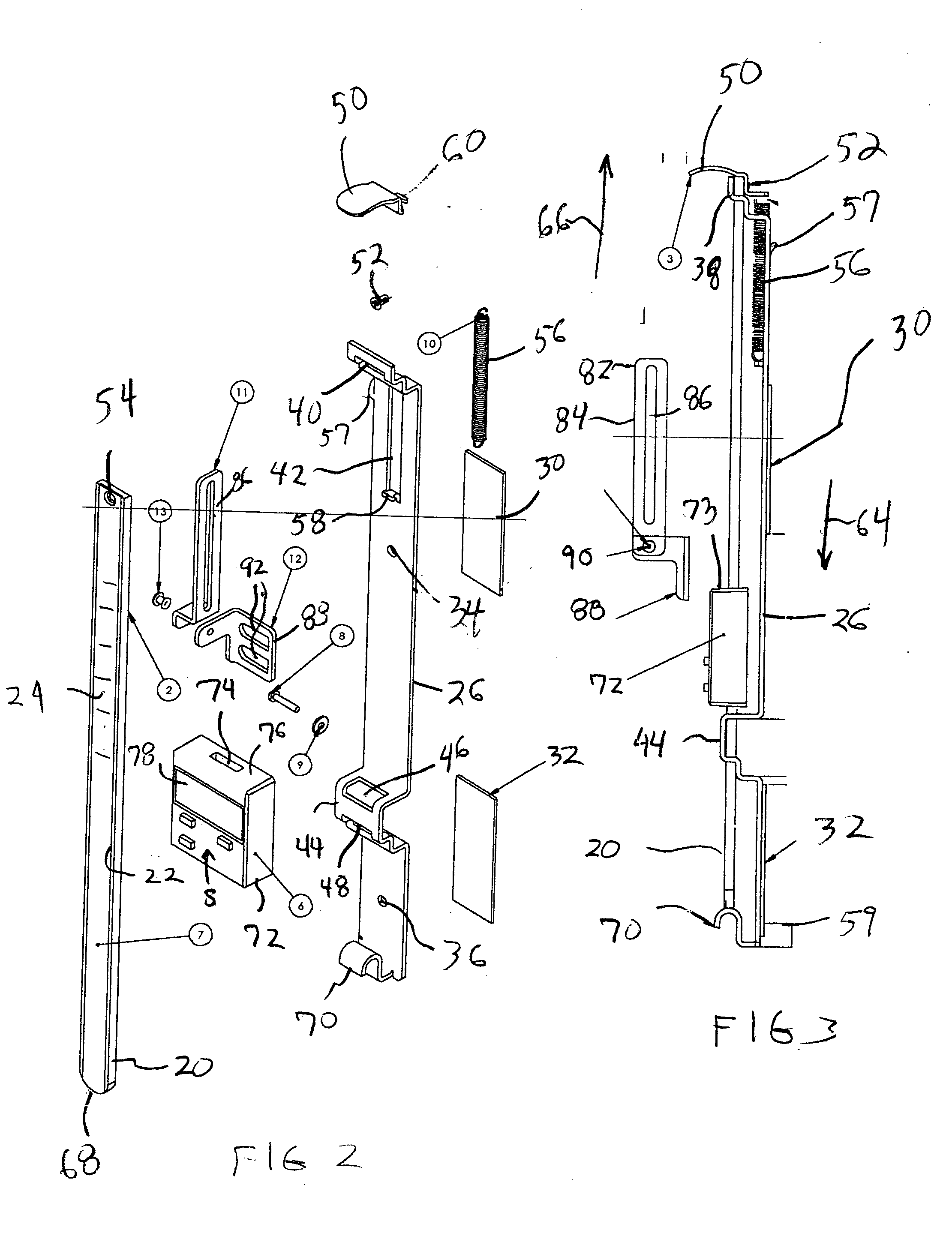
[0022]FIG. 2 is an exploded view of the digital measurement system;

[0023]FIG. 3 is a side elevational view of the measurement system;

[0024]FIG. 4 is a perspective view of the upper end of the measurement system, particularly illustrating how the measurement system is initially engaged with the housing or casing of the machine;

[0025]FIG. 5 is a perspective view of the lower end of the measurement system in a position analogous to that shown in FIG. 4;

[0026]FIGS. 6 and 7 are perspective views depicting installation of the digital readout;

[0027]FIG. 8 is a perspective view illustrating an alternative installation arrangement for the digital readout;

[0028]FIG. 9 is a front ...


PUM


Abstract

A digital measurement system is provided for an apparatus including first and second parts that are positionally adjustable relative to one another, the first part having a base surface and the second part being selectively adjustable toward and away from the base surface. The measurement system includes an elongate reference element mounted for longitudinal movement on the first part such that a first end of the reference element is positionable to be substantially even with the base surface of the first part. A digital reader head is attachable to the second part. The reader head is operable is operably engaged with and moveable along the reference element for measuring relative movement of the reader head along the reference element. The readout further includes a digital display for indicating a measurement corresponding to the relative movement of the reader head along the reference element.

Description

RELATED APPLICATION [0001] This application claims the benefit of U.S. Provisional Application Ser. No. 60 / 467,326, filed May 5, 2003, and 60 / 492,111, filed Aug. 4, 2003.FIELD OF THE INVENTION [0002] This invention relates to a digital measurement system and more particularly to a system for providing accurately calibrated digital measurements in woodworking machines and other types of machinery tools and applications. BACKGROUND OF THE INVENTION [0003] Woodworking machines, such as planers and sanders, as well as various other dimensionally adjustable tools employ digital readouts that measure the height, length or thickness of the piece on which the tool is working. Properly calibrating the readout device tends to be problematic. For example, in planers and sanders, the readout is typically mounted to a height-adjustable cutting head. In order to avoid damage to the cutting blades, this head is normally not allowed to engage the wood-supporting table of the machine. As a result, i...

Claims


Application Information

Patent Timeline
IPC IPC(8): B27C1/14G01B5/06G01D21/00
CPCG01B5/061B27C1/14
Inventor WIXEY, BARRY
Owner WIXEY BARRY
Learn More