Investment casting method and cores and dies used therein

Inactive Publication Date: 2005-01-13
GENERAL ELECTRIC CO
View PDF8 Cites 55 Cited by
  • Summary
  • Abstract
  • Description
  • Claims
  • Application Information

AI Technical Summary

Problems solved by technology

Using this method to produce parts with internal channels is complicated by the need for the ceramic shell to include internal mold cores that define the channels.
These ceramic mold cores are often formed by injection molding, and as the desired cooling channel configuration for an airfoil component becomes more complicated, the ability to form the required mold cores becomes more difficult due to the demands placed upon the injection molding process to completely fill convoluted, narrow pa

Method used


Image

  • Investment casting method and cores and dies used therein
  • Investment casting method and cores and dies used therein

Examples


Embodiment Construction

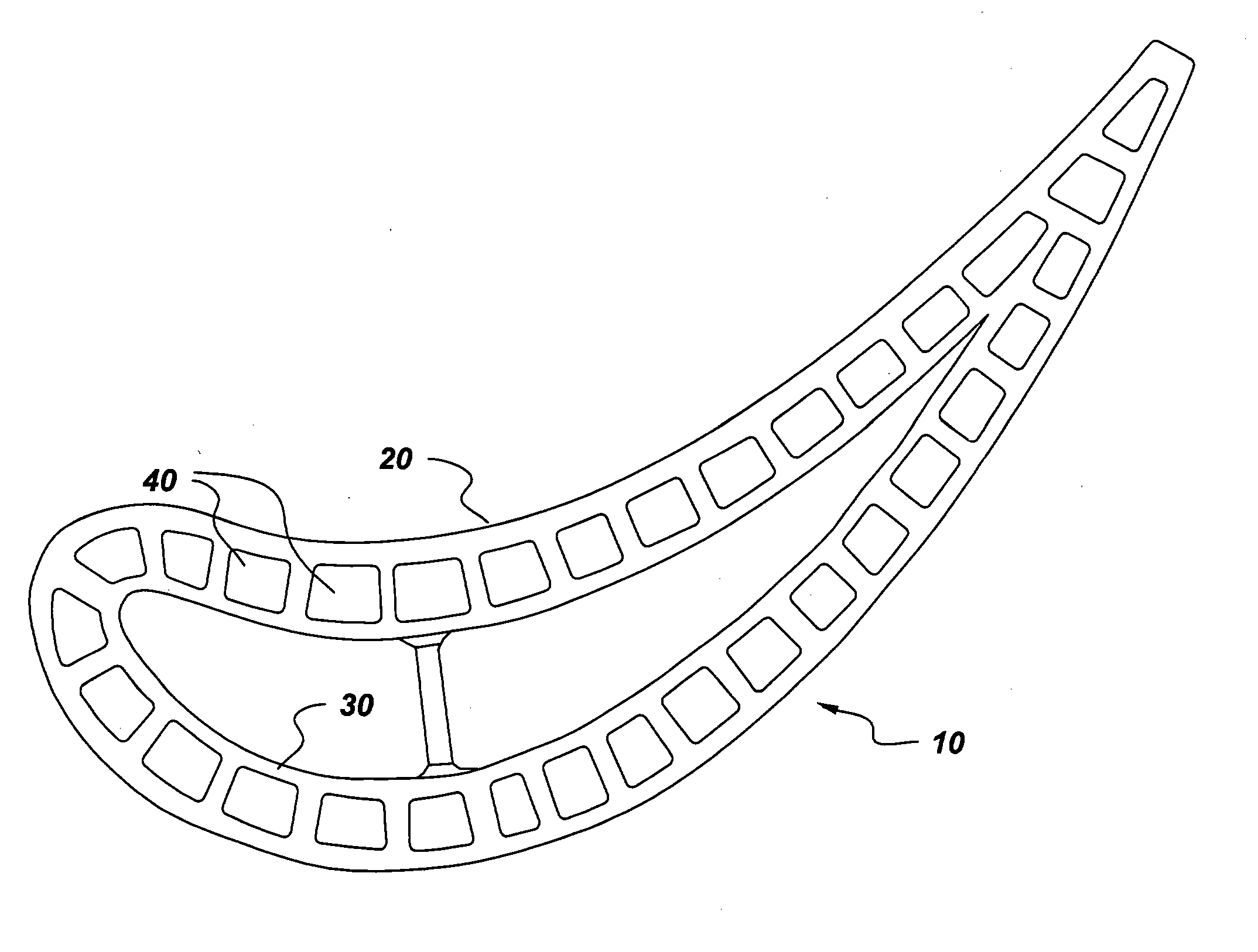
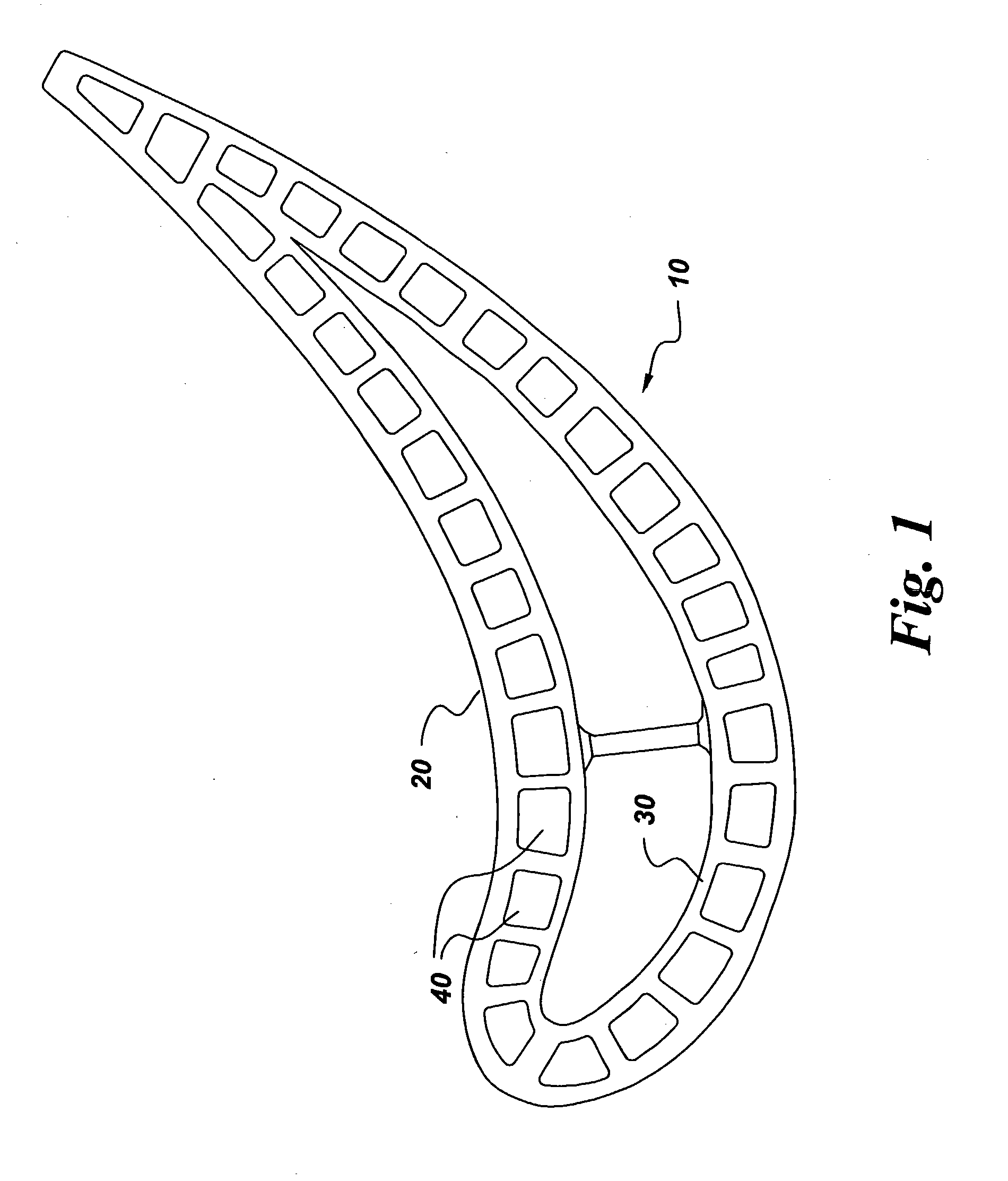
[0012] Referring to FIG. 1, a component 10 is made according to method embodiments of the present invention. In particular embodiments, component 10 comprises an external wall 20 and at least one internal wall 30 disposed in a spaced-apart relationship with external wall 20. Such components are referred to herein as “multi-wall components.” In the method of the present invention, a single-piece sacrificial die is provided. Conventional dies are generally constructed to be used multiple times and are usually two-piece designs, but the complicated geometry of the cooling circuits used in multi-wall components 10 makes the use of dies having two pieces very difficult and often impossible, requiring in conventional methods additional time and effort for multiple injected cores to be formed and assembled into a composite core. The single-piece sacrificial die comprises at least one internal cavity. As used hereinafter, the singular term “cavity” will be used to refer to the at least one ...


PUM

PropertyMeasurementUnit
Structureaaaaaaaaaa

Abstract

A method for making an article by an investment casting process is presented, along with a method for making casting cores, the casting cores made by this method, and dies for making such cores. The method for making a component comprises providing a single-piece sacrificial die, the die comprising at least one internal cavity; introducing a ceramic slurry into the at least one cavity of the die, the slurry comprising a ceramic and a carrier fluid; curing the slurry to form a ceramic casting core; removing the sacrificial die by exposing the die to an environment adapted to destroy the die while leaving the ceramic casting core intact; and performing an investment casting process using the ceramic casting core as part of a mold-core assembly to form the component.

Description

BACKGROUND OF THE INVENTION [0001] This invention relates to investment casting of complex articles. More particularly, this invention relates to the manufacture and use of integral, sacrificial cores for investment casting complex articles. [0002] In a gas turbine engine, compressed air is mixed with fuel in a combustor and ignited, generating a flow of hot combustion gases through one or more turbine stages that extract energy from the gas, producing output power. Each turbine stage includes a stator nozzle having vanes that direct the combustion gases against a corresponding row of turbine blades extending radially outwardly from a supporting rotor disk. The vanes and blades include airfoils having a generally concave “pressure” side and a generally convex “suction” side, both sides extending axially between leading and trailing edges over which the combustion gases flow during operation. The vanes and blades are subject to substantial heat load, and, because the efficiency of a ...

Claims


Application Information

Patent Timeline
IPC IPC(8): B22C9/04B22C9/10B29C67/00
CPCB29C67/0051B22C9/10B33Y80/00Y02P10/25
Inventor WANG, HSIN-PANGLEE, CHING-PANG
Owner GENERAL ELECTRIC CO
Why Eureka
Try Eureka