Magnetic core and coil component using the same

a technology of magnetic core and coil component, applied in the direction of magnetic core/yokes, transformer/inductance magnetic core, magnetic bodies, etc., can solve the problems of jp coil component, dc bias characteristic drastically saturated, relative permeability lowered,

Inactive Publication Date: 2005-01-13
TOKIN CORP
View PDF22 Cites 50 Cited by
  • Summary
  • Abstract
  • Description
  • Claims
  • Application Information

AI Technical Summary

Problems solved by technology

Furthermore, according to conventional techniques, beyond the target electric-current range, its DC bias characteristic becomes drastically saturated and its relative permeability becomes lowered.
It is therefore conceivable that the coil component of JP-A 2001-185421 is not suitable for the high-power system.

Method used


Image

  • Magnetic core and coil component using the same
  • Magnetic core and coil component using the same
  • Magnetic core and coil component using the same

Examples


Embodiment Construction

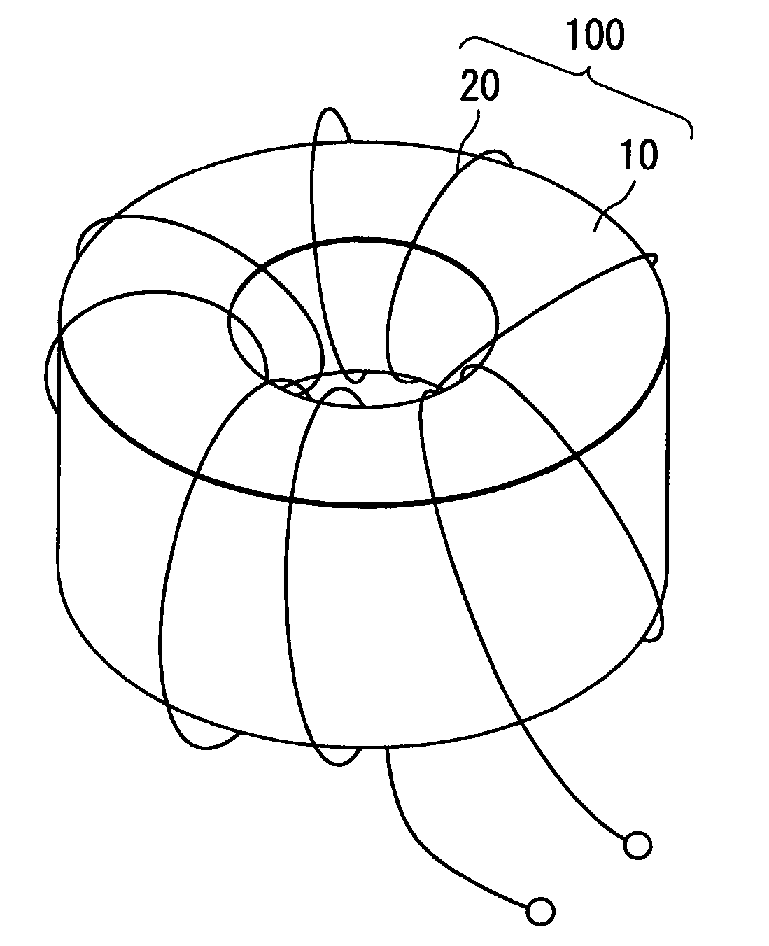
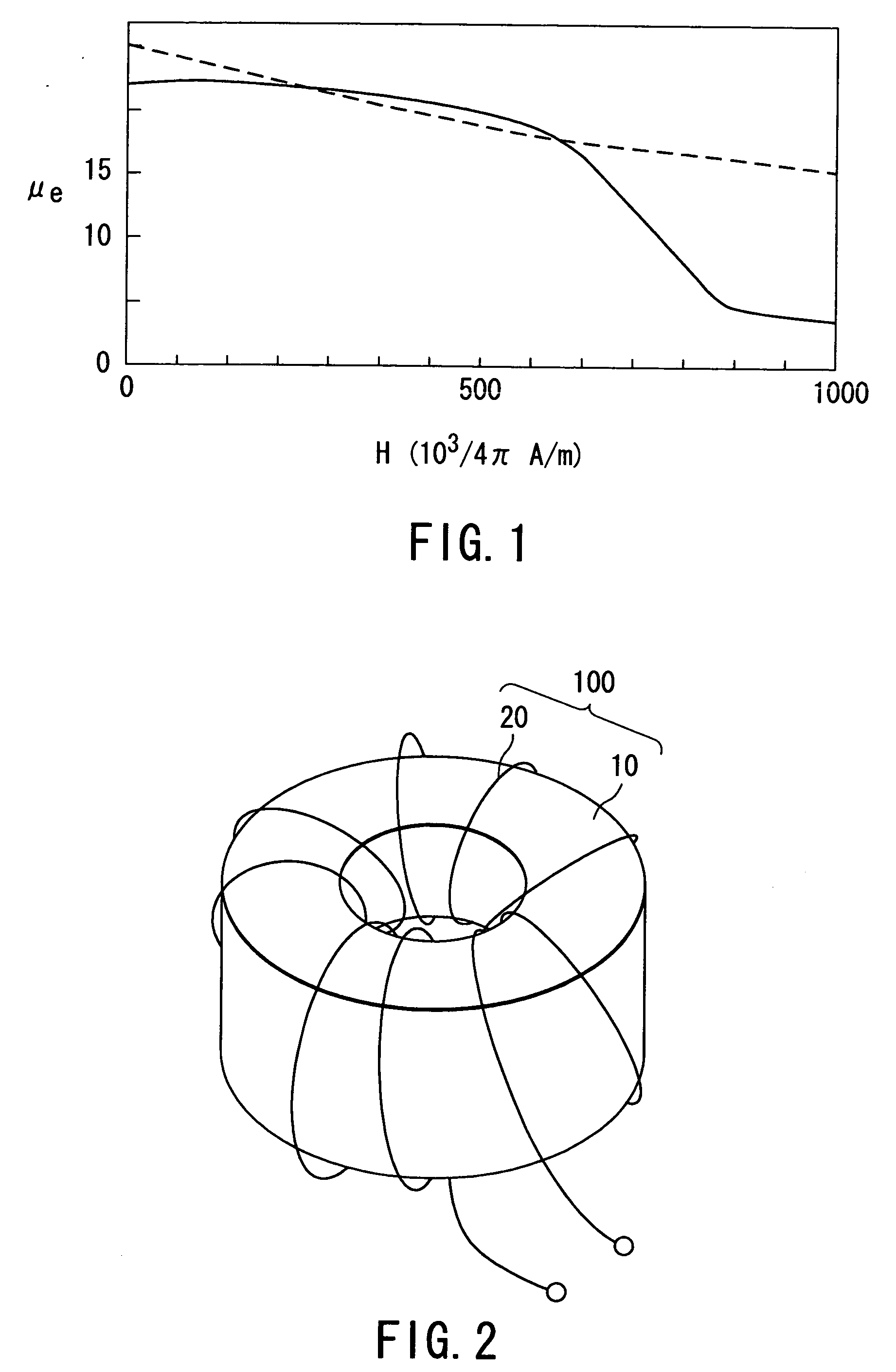
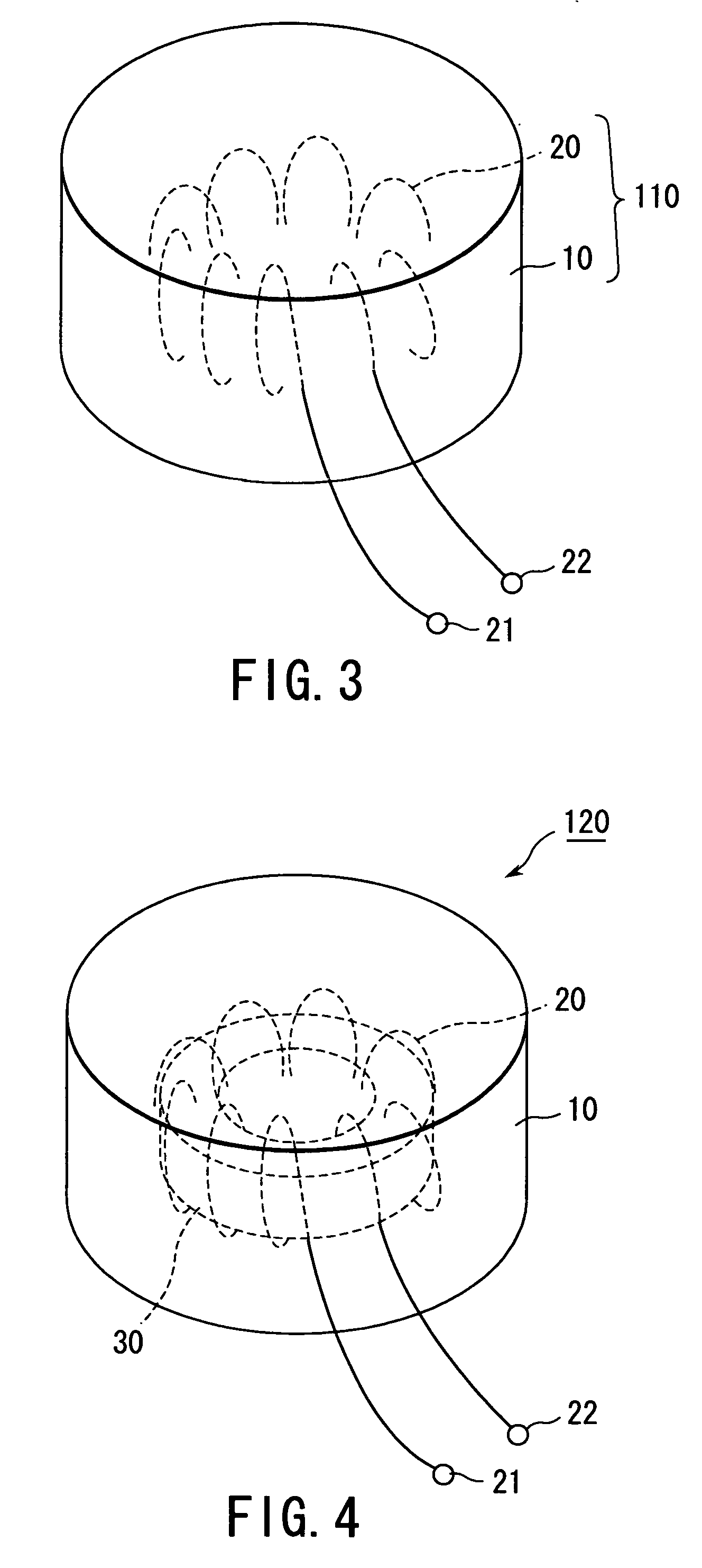
[0020] According to an embodiment of the present invention, a magnetic core is made of a mixture of magnetic powder and resin. In detail, the magnetic core of the embodiment is a casting, which is obtainable by casting the mixture into a predetermined shaped container for molding. In consideration of the size of the high-power coil component, it is preferable that the mixture is composed of the materials which are capable of casting without any solvents.

[0021] In this embodiment, the casting process is basically carried out without pressure or with reduction of pressure. Once the casting process is finished, the casting may be subjected to some pressure for the purpose of increasing the density of the magnetic core according to the present embodiment. There is no limitation on the mold shape, and the magnetic core of the mixture can be formed in any shapes.

[0022] The magnetic powder is soft magnetic metal powder, especially, Fe base powder in this embodiment. Specifically, the Fe ...


PUM

PropertyMeasurementUnit
elastic modulusaaaaaaaaaa
diameteraaaaaaaaaa

Abstract

A magnetic core is obtained by hardening or curing a mixture of magnetic powder and resin. The magnetic core shows a superior DC bias characteristic which does not become drastically saturated but is gently saturated even beyond 1000*103 / 4π [A / m]. Therefore, the magnetic core has sufficient relative permeability more than ten.

Description

BACKGROUND OF THE INVENTION [0001] This invention relates to a magnetic core and a coil component using the same. In particular, his invention relates to the magnetic core for the coil component which is used as a reactor in a high-power system such as an energy control of a battery mounted on an electrically-powered car or a hybrid car including an electromotor and an internal-combustion engine. [0002] A known coil component is disclosed in JP-A2001-185421. The disclosed coil component is used for a low-power system. The disclosed coil component comprises a coil and first and second magnetic core members. The first magnetic core member includes magnetic metal powder of 50-70%, by volume, and thermosettable resin of 50-30%, by volume. The second magnetic core member is a dust core made of sintered ferrite body or magnetic metal powder. The first and the second magnetic core members are magnetically connected in series. The coil is embedded in the first magnetic core member. [0003] O...

Claims


Application Information

Patent Timeline
Patent Type & Authority Applications(United States)
IPC IPC(8): H01F1/147H01F1/153H01F1/24H01F3/08H01F17/06H01F41/00H01F41/02
CPCH01F1/1475H01F1/15366H01F1/24H01F3/08H01F2017/048H01F41/005H01F41/0246H01F2017/046H01F17/062H01F27/24
Inventor ONO, KAZUYUKIYANBE, TAKASHIMATSUMOTO, HATSUO
Owner TOKIN CORP
Why Eureka
Try Eureka