Supercharge Your Innovation With Domain-Expert AI Agents!

Liquid discharge detection method and apparatus and ink-jet printer apparatus

a detection method and liquid discharge technology, applied in the direction of speed/acceleration/shock measurement, printing, instruments, etc., can solve the problems of low detection accuracy, large cost, and low reliability of liquid discharge droplets, and achieve the effect of accurate detection

Inactive Publication Date: 2005-01-13
CANON KK
View PDF7 Cites 5 Cited by
  • Summary
  • Abstract
  • Description
  • Claims
  • Application Information

AI Technical Summary

Benefits of technology

The present invention provides a method and apparatus for detecting when liquid is discharged from a head in an ink-jet printer. The invention can accurately detect if liquid is discharged without using high voltage, even with a small amount of liquid. This technology allows for improved accuracy and efficiency in detecting liquid discharge, which can improve the overall performance and reliability of ink-jet printers.

Problems solved by technology

The disclosed technique of detecting the discharge / non-discharge on ink, however, has the following problems.
However, the charge given to an ink droplet concentrates on the surface of the ink droplet, and hence the detectivity based on such an ink droplet is low.
If the amount of ink discharged is small, in particular, only a slight output can be obtained, posing a problem in terms of reliability.
This, however, requires an enormous cost, and a high voltage is generated and applied inside the apparatus, posing a problem in terms of safety.
This takes more time, and the amount of ink waste increases because a plurality of ink droplets are discharged.
It is therefore difficult to detect a fluctuation or variation in each ink droplet.

Method used


Image

  • Liquid discharge detection method and apparatus and ink-jet printer apparatus
  • Liquid discharge detection method and apparatus and ink-jet printer apparatus
  • Liquid discharge detection method and apparatus and ink-jet printer apparatus

Examples


first embodiment

[0024] [First Embodiment]

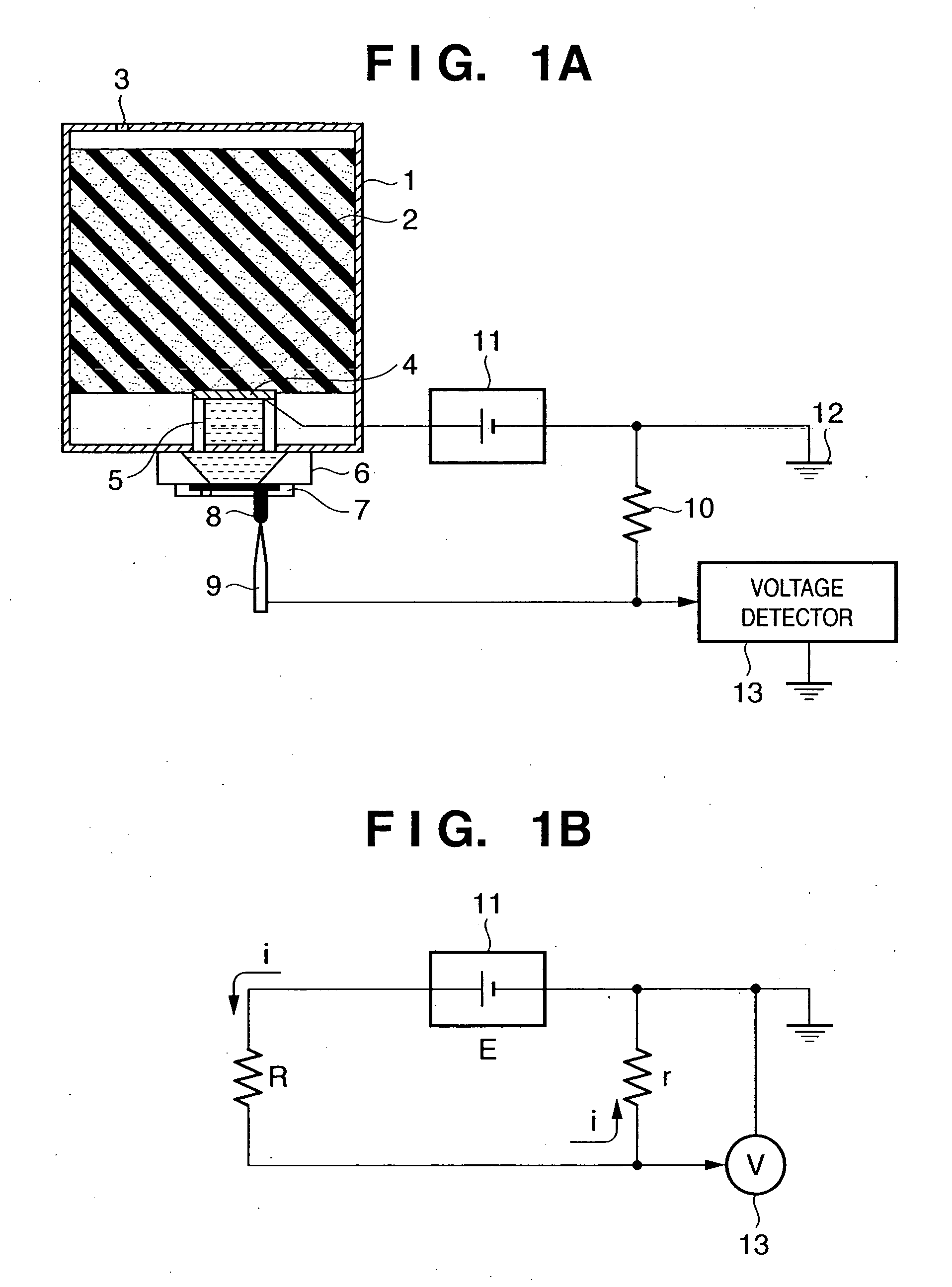
[0025]FIGS. 1A and 1B depict views for explaining the detection of ink discharge according to the first embodiment of the present invention. FIG. 1A is a view for explaining the principle of the detection. FIG. 1B is an equivalent circuit diagram for explaining an equivalent circuit at the time of ink detection.

[0026] An ink absorber 2 is housed in an ink cartridge 1, and ink is absorbed and held by the capillary attraction of the ink absorber 2. Ink is supplied from the ink absorber 2 to an ink-jet head 6 via a filter 4 for filtering dust and the like and a channel 5 serving as an ink channel. Reference numeral 3 denotes an air hole formed in the ink cartridge 1. The ink-jet head 6 has a nozzle layer 7 which is formed of a resin or the like and has a nozzle for discharging ink. In each nozzle layer 7, ink is heated and foamed by a discharge heater (not shown) provided on an element board in correspondence with each nozzle, and is discharged outside from th...


PUM


Abstract

In a liquid discharge detection method and apparatus which detect a liquid discharged from a liquid discharge head, an electrode is placed at a position where the liquid discharged from the liquid discharge head comes into contact with the electrode while being in contact with the head. When a liquid is discharged, and the head is connected to the electrode through the liquid, the circuit becomes a closed circuit. A voltage generated between the two ends of a resistor r is obtained from a current i flowing in the closed circuit. When this voltage becomes equal to or higher than a predetermined voltage, liquid discharge can be detected.

Description

TECHNICAL FIELD [0001] The present invention relates to a liquid discharge detection method and apparatus which detect the discharge state of a liquid from a head, and an ink-jet printer apparatus. BACKGROUND ART [0002] Conventionally, as a method of detecting the discharge / non-discharge of ink from an ink-jet head or the discharge state of ink, for example, the ink droplet detector disclosed in Japanese Patent Laid-Open No. 11-170569 is available. This detector has a function of determining the discharge state of ink from the ink-jet head. Upon detecting a nozzle that discharges no ink, the detector notifies the user of the ink-jet printer of an error warning or the like, thereby allowing the user to prevent from printing any faulty image. [0003] The disclosed technique of detecting the discharge / non-discharge on ink, however, has the following problems. [0004] (1) An ink droplet is charged, and whether ink is discharged or not is detected by detecting charge (induced charge) when ...

Claims


Application Information

Patent Timeline
Patent Type & Authority Applications(United States)
IPC IPC(8): B05B1/16B41J2/01B41J2/045B41J2/055B41J2/12B41J2/125B41J2/14B41J2/165B41J29/38B41J29/393G01P13/00
CPCB41J2/12B41J2/125B41J29/393B41J2/16579B41J2/14096B41J2/045B41J2/01
Inventor MURAYAMA, HIROYUKIISHINAGA, HIROYUKIMISUMI, YOSHINORIMATSUI, TAKAHIRO
Owner CANON KK
Features
  • R&D
  • Intellectual Property
  • Life Sciences
  • Materials
  • Tech Scout
  • Unparalleled Data Quality
  • Higher Quality Content
  • 60% Fewer Hallucinations
Learn More