Transmissive liquid crystal display device having a cholesteric liquid crystal color filter and method of fabricating the same

Active Publication Date: 2005-01-13
LG DISPLAY CO LTD
View PDF6 Cites 1 Cited by
  • Summary
  • Abstract
  • Description
  • Claims
  • Application Information

AI Technical Summary

Benefits of technology

[0023] An advantage of the present invention is to provide a CCF type transmissive liquid crystal display device that does not have a color mixture in borders among the CCFs.
[0024] Another advantage of the present invention is to provide a CCF type transmissive liquid crystal display device that has an improved color display.

Problems solved by technology

A transmissive LCD device requires a high, initial brightness light source, and thus electrical power consumption by the backlight device increases.
A relatively heavy battery is needed to supply sufficient power to the backlight of such a device, and the battery can not be used for a lengthy period of time.
However, the reflective LCD device is affected by its surroundings.
Therefore, the reflective LCD device can not be used where the ambient light is weak or does not exist.
Furthermore, the reflective LCD device has a problem of poor brightness because the ambient light passes through the color filter substrate and is reflected toward the color filter substrate by a reflector on the array substrate.
Namely, because the ambient light passes through the color filter substrate twice, the reflective LCD device has a low light transmissivity and thus, poor brightness.
However, a limitation is encountered when lowering the color purity because it is difficult to form a color filter thickness under a critical margin using a color resin.
Moreover, there are some other problems when forming the R, G and B CCFs in the ratio of 1:1:1.
When the steps (i.e., the thickness differences) exist in the CCF layer, they lead to the different cell gaps in the pixel between the color filter substrate and the array substrate, thereby bringing about a result of retardation difference.

Method used


Image

  • Transmissive liquid crystal display device having a cholesteric liquid crystal color filter and method of fabricating the same
  • Transmissive liquid crystal display device having a cholesteric liquid crystal color filter and method of fabricating the same
  • Transmissive liquid crystal display device having a cholesteric liquid crystal color filter and method of fabricating the same

Examples


Embodiment Construction

[0038] Reference will now be made in detail to embodiments of the present invention, example of which is illustrated in the accompanying drawings. Wherever possible, the same reference numbers will be used throughout the drawings to refer to the same or like parts.

[0039]FIG. 4A is a plan view illustrating a color filter substrate having the cholesteric liquid crystal color filter according to the present invention, and FIG. 4B is a plan view illustrating an array substrate according the present invention.

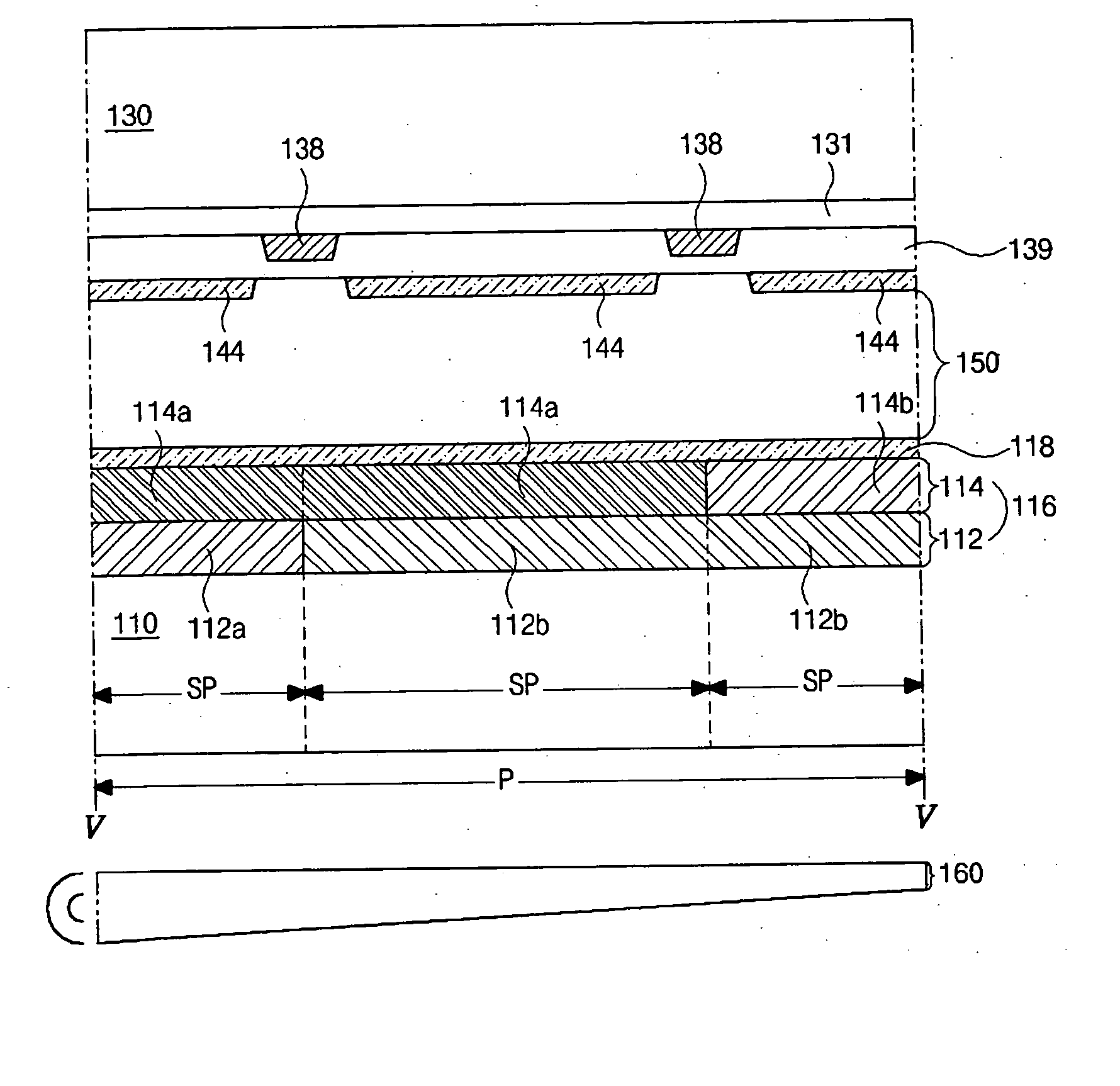
[0040] In FIG. 4A, a pixel P including three sub-pixels SP is defined on a first substrate 110. The three sub-pixels SP have the same size at the ratio of 1:1:1. And a double-layered cholesteric liquid crystal color filter (CCF) layer 116 including first and second CCF layers 112 and 114 is formed on the fist substrate 110. Although the sub-pixels SP have the same size in the ratio of 1:1:1, two of the sub-pixels SP have the same colored CCFs 112b or 114a and the other one sub-pix...


PUM


Abstract

A liquid crystal display device of the present invention includes: first and second substrates including a plurality of pixels, wherein each pixel divided into first to third sub-pixels; a double-layered cholesteric liquid crystal color filter (CCF) layer over the first substrate, the double-layered CCF layer including a first CCF layer including first and second CCF with a ratio of 1:2 in size and a second CCF layer including third and fourth CCF with a ratio of 2:1 in size; a first transparent electrode on the double-layered CCF layer; a second transparent electrode on the second substrate; a liquid crystal layer between the first and second transparent electrodes; and a backlight device adjacent to the first substrate and emitting light toward the first and second substrates.

Description

[0001] This application claims the benefit of Korean Patent Application No. 2003-0045991, filed on Jul. 8, 2003, which is hereby incorporated by reference for all purposes as if fully set forth herein. BACKGROUND OF THE INVENTION [0002] 1. Field of the Invention [0003] The present invention relates to a liquid crystal display device, and more particularly to a transmissive liquid crystal display device using a cholesteric liquid crystal color filter layer. [0004] 2. Discussion of the Related Art [0005] Liquid crystal display (LCD) devices with light, thin, and low power consumption characteristics are used in office automation equipment, video units and the like. Such LCDs typically use a liquid crystal (LC) interposed between upper and lower substrates with an optical anisotropy. Because the LC has thin and long LC molecules, the alignment direction of the LC molecules can be controlled by applying an electric field to the LC molecules. When the alignment direction of the LC molecu...

Claims


Application Information

Patent Timeline
IPC IPC(8): G02F1/1335
CPCG02F1/133514G02F1/1335
Inventor MOON, JONG-WEONHUR, JAE-HONG
Owner LG DISPLAY CO LTD
Why Eureka
Try Eureka