
Method and device for changing image size

a technology of image size and image, applied in the field of methods and devices for changing image size, can solve the problems of image quality deterioration, flicker on the screen, coarseness becoming conspicuous, etc., and achieve the effect of increasing or reducing the size, without deteriorating the image quality

Inactive Publication Date: 2005-01-13
SEIKO EPSON CORP
View PDF15 Cites 3 Cited by
  • Summary
  • Abstract
  • Description
  • Claims
  • Application Information

AI Technical Summary

Benefits of technology

[0006] Accordingly, the present invention may provide a method and a device for changing an image size which can increase or reduce the size of the original image having a processing history of compression or decompression in units of unit areas without deteriorating the image quality.
[0015] In the present invention, since data in the first boundary pixel is prevented from being used as interpolation data, the image quality can be maintained even if the image size is increased in the horizontal direction.
[0018] Since data in the second boundary pixel is prevented from being used as interpolation data, the image quality can be maintained even if the image size is increased in the vertical direction.
[0021] Since data in the first boundary pixel is prevented from being thinned out, the image quality can be maintained even if the image size is reduced in the horizontal direction.
[0024] Since data in the second boundary pixel is prevented from being thinned out, the image quality can be maintained even if the image size is reduced in the vertical direction.
[0028] The data interpolation step may include obtaining data in the interpolation pixel by averaging data in pixels adjacent to the interpolation pixel. The data thinning step may include averaging data in a pixel that is adjacent to the thinning pixel and other than the first or second boundary pixels by using the thinning pixel. This reduces emphasis of brightness or color in comparison with the case where data is not averaged, whereby an image quality close to that of the original image can be maintained.

Problems solved by technology

However, a flicker occurs on the screen or coarseness becomes conspicuous when this method is used for an image having a processing history of MPEG-4 compression or decompression, whereby the image quality deteriorates.

Method used


Image

  • Method and device for changing image size
  • Method and device for changing image size
  • Method and device for changing image size

Examples


Embodiment Construction

[0048] An embodiment of the present invention is described below with reference to the drawings.

[0049] Outline of Portable Telephone

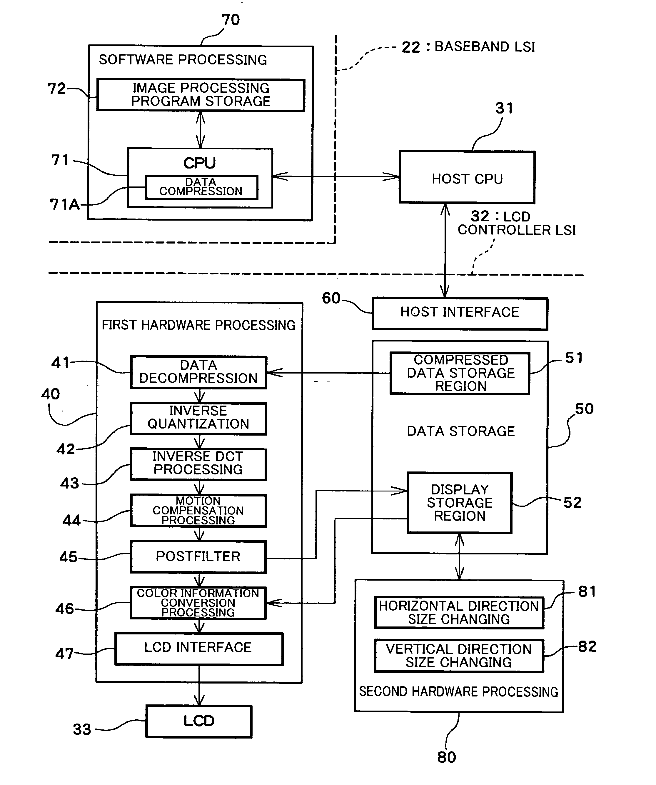
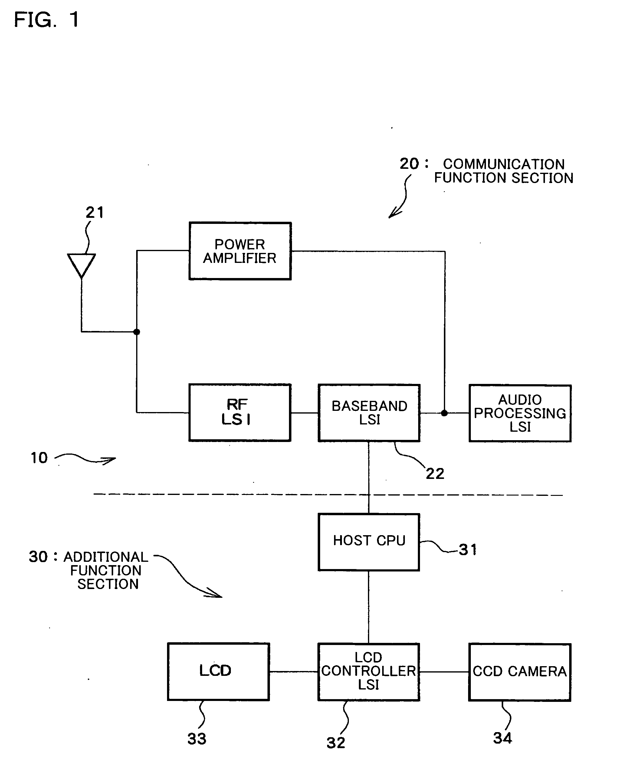
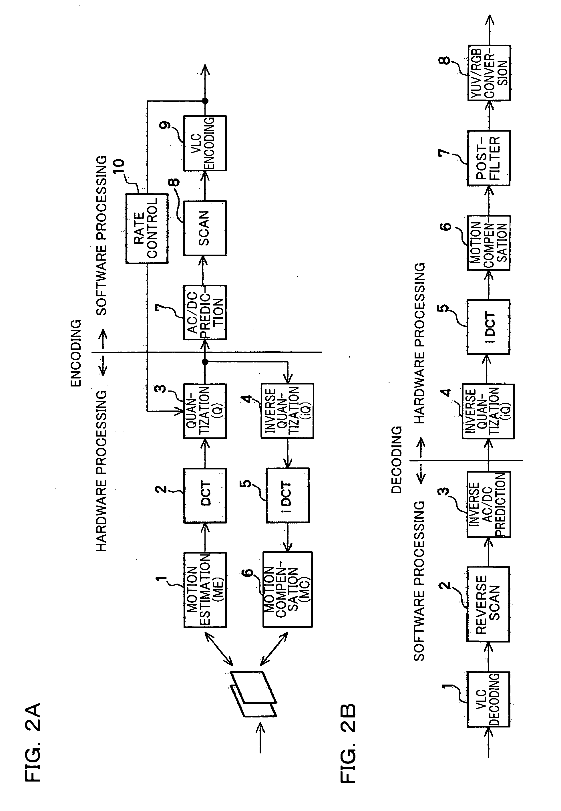
[0050]FIG. 1 is a block diagram of a portable telephone which is an example of an electronic instrument to which the present invention is applied. In FIG. 1, a portable telephone 10 is roughly divided into a communication function section 20 and an additional function section 30. The communication function section 20 includes various conventional blocks which process a signal (including a compressed moving image) transmitted and received through an antenna 21. A baseband LSI 22 in the communication function section 20 is a processor which mainly processes voice or the like, and is necessarily provided in the portable telephone 10. The baseband LSI 22 is provided with a baseband engine (BBE), an application processor, and the like. Software on the processor performs MPEG-4 compression (encode) processing shown in FIG. 2A, including variable length code...


PUM


Abstract

A method of changing an image size includes changing a size of the original image at least in a horizontal direction by interpolating data in an interpolation pixel between predetermined pixels in each of the unit areas of the original image according to a set horizontal increasing scale factor. Each of the unit areas includes a plurality of first boundary pixels arranged along a vertical virtual boundary line between two of the unit areas adjacent in the horizontal direction in the frame. In the image size changing step, the interpolation pixel is set between pixels other than the first boundary pixels.

Description

[0001] Japanese Patent Application No. 2003-150847, filed on May 28, 2003, is hereby incorporated by reference in its entirety. BACKGROUND OF THE INVENTION [0002] The present invention relates to a method and a device for changing an image size which can change the size of an original image having a processing history of Moving Picture Experts Group (MPEG) compression or decompression or the like. [0003] Conventionally, data is interpolated in interpolation pixels between pixels when increasing the image size, and data in thinning pixels is omitted when reducing the image size. [0004] However, a flicker occurs on the screen or coarseness becomes conspicuous when this method is used for an image having a processing history of MPEG-4 compression or decompression, whereby the image quality deteriorates. [0005] The present inventors have found that processing performed during compression or decompression in units of unit areas, which are defined by diving one frame, is relevant to deter...

Claims


Application Information

Patent Timeline
IPC IPC(8): G06K9/32G06K9/36G06T3/40G09G5/00G09G5/36G09G5/397G09G5/399H04N1/393H04N5/262H04N9/80H04N19/50H04N19/59H04N19/625H04N19/86H04N19/91
CPCH04N19/527G06T3/4007
Inventor KONDO, YOSHIMASASHINDO, TAKASHI
Owner SEIKO EPSON CORP
Learn More