
Connector for connecting printed circuit boards

a technology for connecting printed circuit boards and printed circuit boards, applied in the direction of coupling device connections, coupling contact members, coupling device details, etc., can solve the problems of invariably expensive new developments for specific predetermined geometry and the number of contacting options, and achieve the effect of increasing the density of signal lines

Inactive Publication Date: 2005-01-13
WHITE BOX +1
View PDF16 Cites 36 Cited by
  • Summary
  • Abstract
  • Description
  • Claims
  • Application Information

AI Technical Summary

Benefits of technology

[0005] Consequently, the invention is based on the objective of developing a connector of the initially described type in such a way that a large quantity of signal lines can be connected, wherein a spherical contact arrangement makes it possible to achieve an impedance-adapted signal transmission with minimal interference of the useful signals, and wherein scalable variations of the contacting arrangement can be realized with the least expenditure possible.

Problems solved by technology

In this edge-board connector, it is disadvantageous that the specifically predetermined geometry and number of contacting options invariably requires costly new developments in order to realize other edge-board connector variations.

Method used


Image

  • Connector for connecting printed circuit boards
  • Connector for connecting printed circuit boards
  • Connector for connecting printed circuit boards

Examples


Embodiment Construction

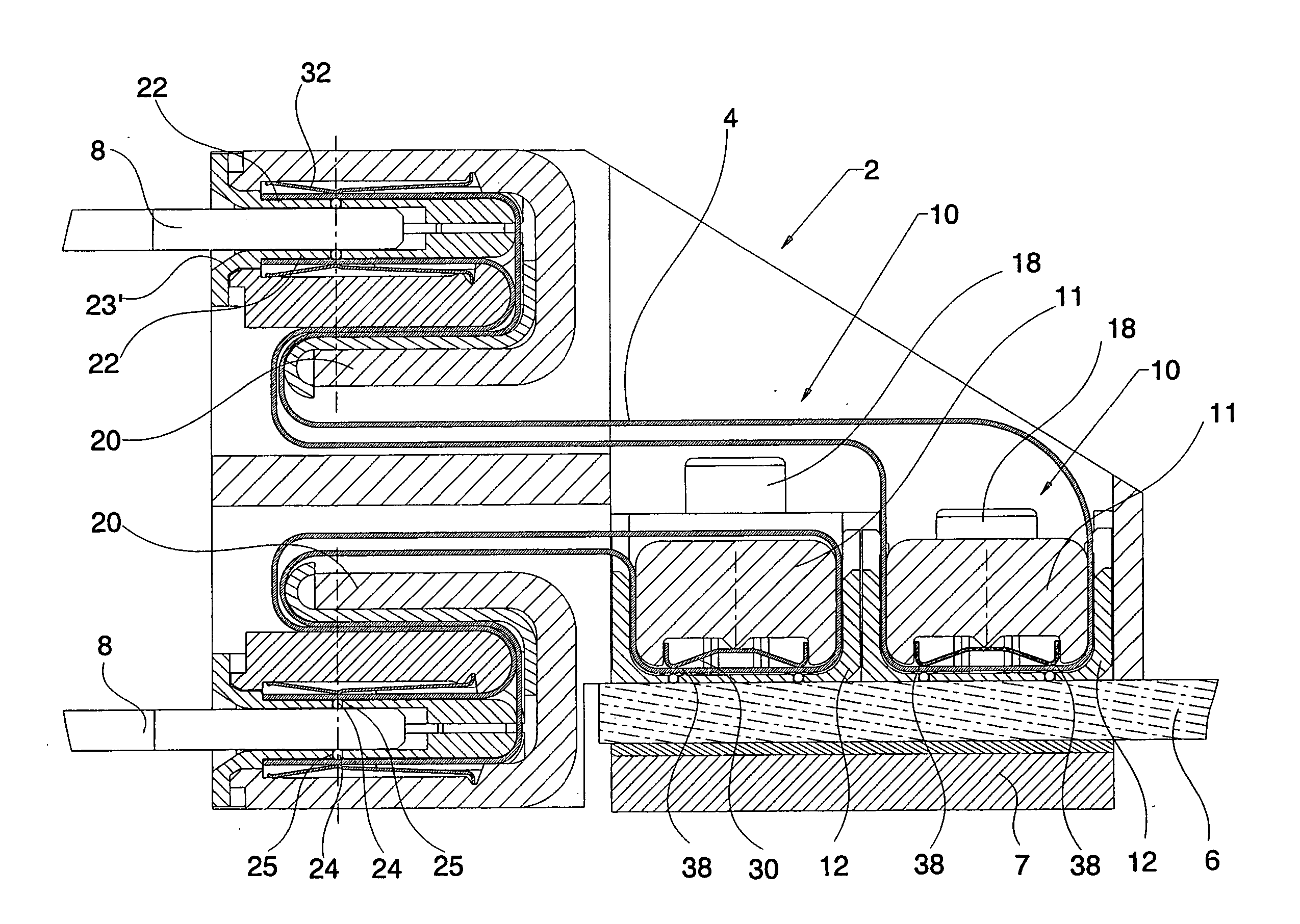
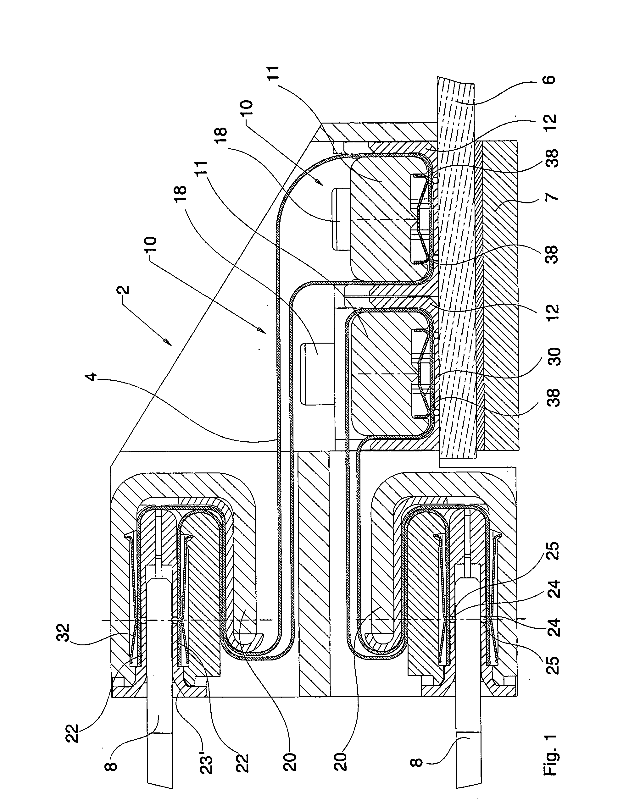
[0017]FIG. 1 shows a section through a connector for connecting printed circuit boards, in which a total of four individual support members are arranged a connector housing 2. In this case, two identical support members 10 that are arranged adjacent to one another and form the terminal side are fixed on a base circuit board 6, wherein two additional support members 20 that are also realized identically and form the mating side of the connector are arranged on top of one another and designed for respectively accommodating a plug-in edge-connector circuit board. The support members are respectively connected to one another within the connector housing by means of flexible conductive foils 4. The two support members 10 are arranged adjacent to one another and connected to the base circuit board 6 by means of a screw connection 18, wherein a transverse reinforcement 7—especially for large printed circuit boards—is provided underneath the base circuit board in order to additionally stabi...


PUM


Abstract

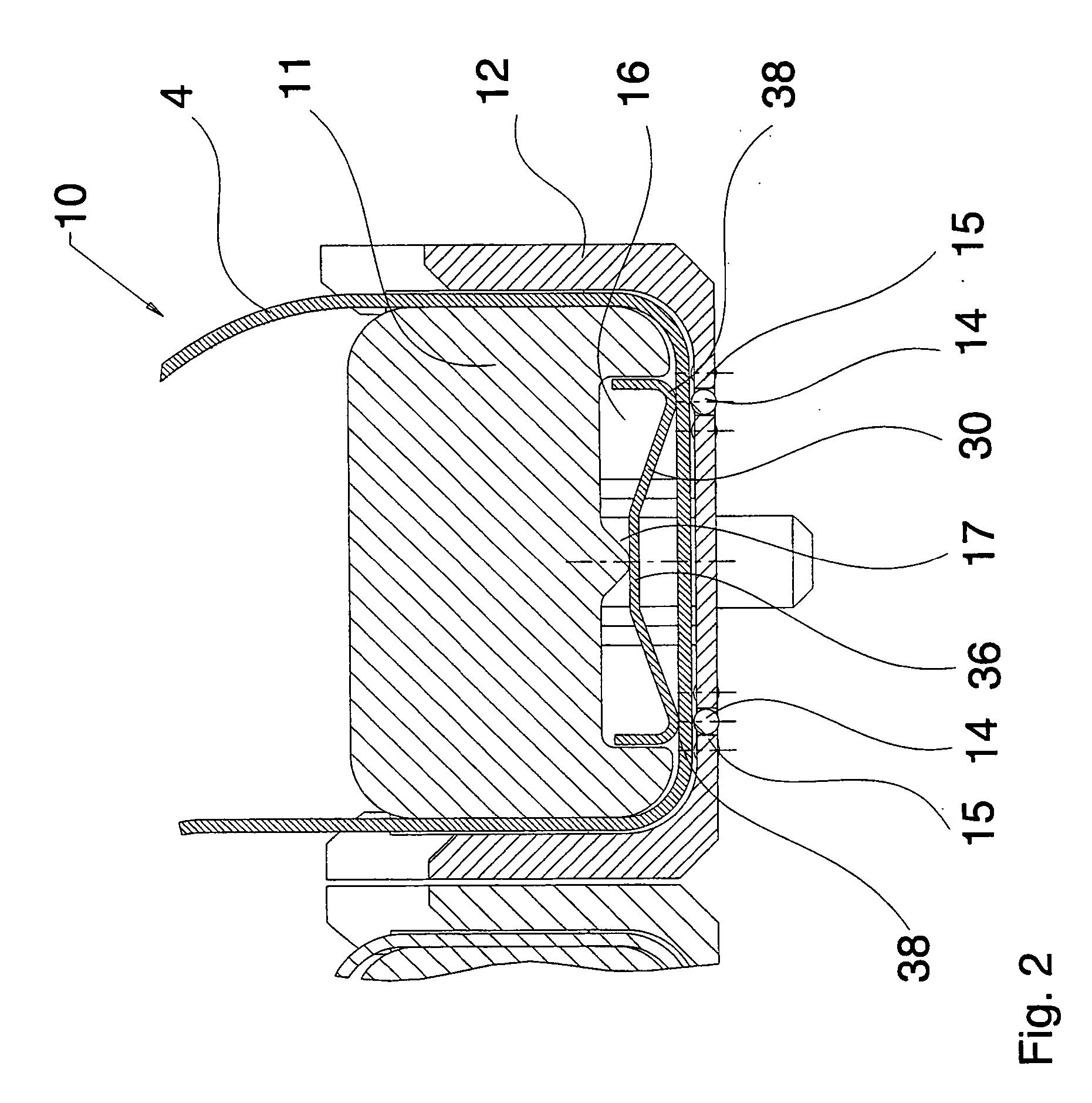
In order to produce an electric connection between at least two printed circuit boards, the invention proposes a connector with a mating side and a terminal side, in which an arrangement of several support members is provided in a housing. Spherical contacts for realizing the electric contacting of the strip conductors are arranged in said support members. At least one first support member is rigidly connected to a base circuit board with a terminal side while at least one second support member with a mating side is provided for inserting an edge-connector circuit board therein. The electric connection between the two support members is realized with strip conductors that are applied on a flexible conductive foil and contacted by the spherical contacts.

Description

TECHNICAL FIELD [0001] The invention pertains to a connector with a mating side and a terminal side for connecting printed circuit boards. BACKGROUND OF THE INVENTION [0002] A connector of this type is required for connecting printed circuit boards with a high signal line density and for high signal clock rates in a solder-free and separable fashion. [0003] U.S. Pat. No. 4,157,857 discloses an edge-board connector for a printed circuit board that is fixed on a base circuit board, wherein spherical contact elements are arranged in a connector housing. The contact elements contact strip conductors on a plug-in printed circuit board on one side and strip conductors on the base circuit board on the other side via spring contacts that are connected in an electrically conductive fashion to a solderable terminal side. BRIEF SUMMARY OF THE INVENTION [0004] In this edge-board connector, it is disadvantageous that the specifically predetermined geometry and number of contacting options invari...

Claims


Application Information

Patent Timeline
IPC IPC(8): H01R4/50H01R12/16H01R13/24
CPCH01R4/5058H01R12/721H01R13/2442
Inventor BURMEISTER, MICHAELKRAUSE, JENS
Owner WHITE BOX
Learn More