Cavity former

Inactive Publication Date: 2005-01-20
AUSTRALIAN STEEL OPERATIONS THE
View PDF21 Cites 14 Cited by
  • Summary
  • Abstract
  • Description
  • Claims
  • Application Information

AI Technical Summary

Benefits of technology

[0007] In accordance with the invention, it has been recognised that transport of cavity formers would be more convenient were the formers, collectively, to have a less voluminous state than their volume ready for the concrete to be poured. This less voluminous state is achievable by providing a suitable

Problems solved by technology

Polystyrene overcomes this limitation, but it has the disadvantage that, when cut into smaller shapes for cavities of smaller sizes, large quantities of fine polystyrene particles are often generated.
Such polystyrene particles present an environmental p

Method used


Image

  • Cavity former
  • Cavity former
  • Cavity former

Examples


first embodiment

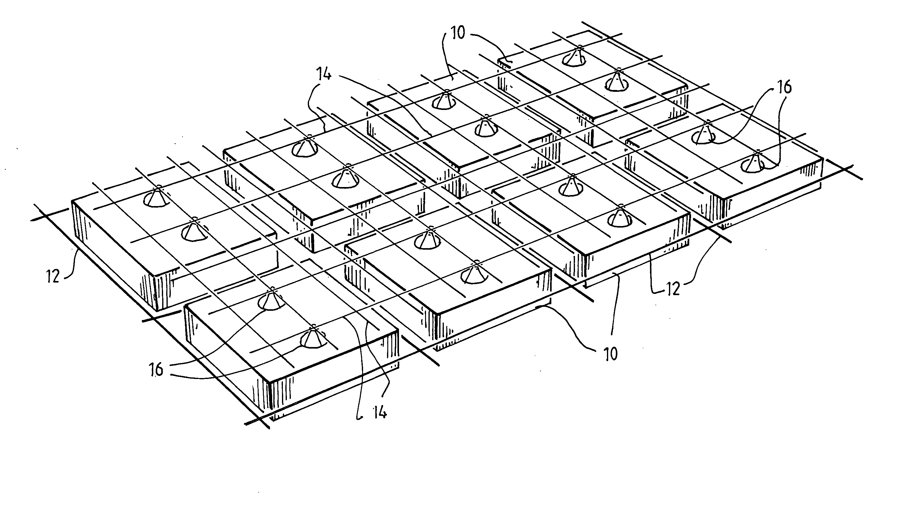
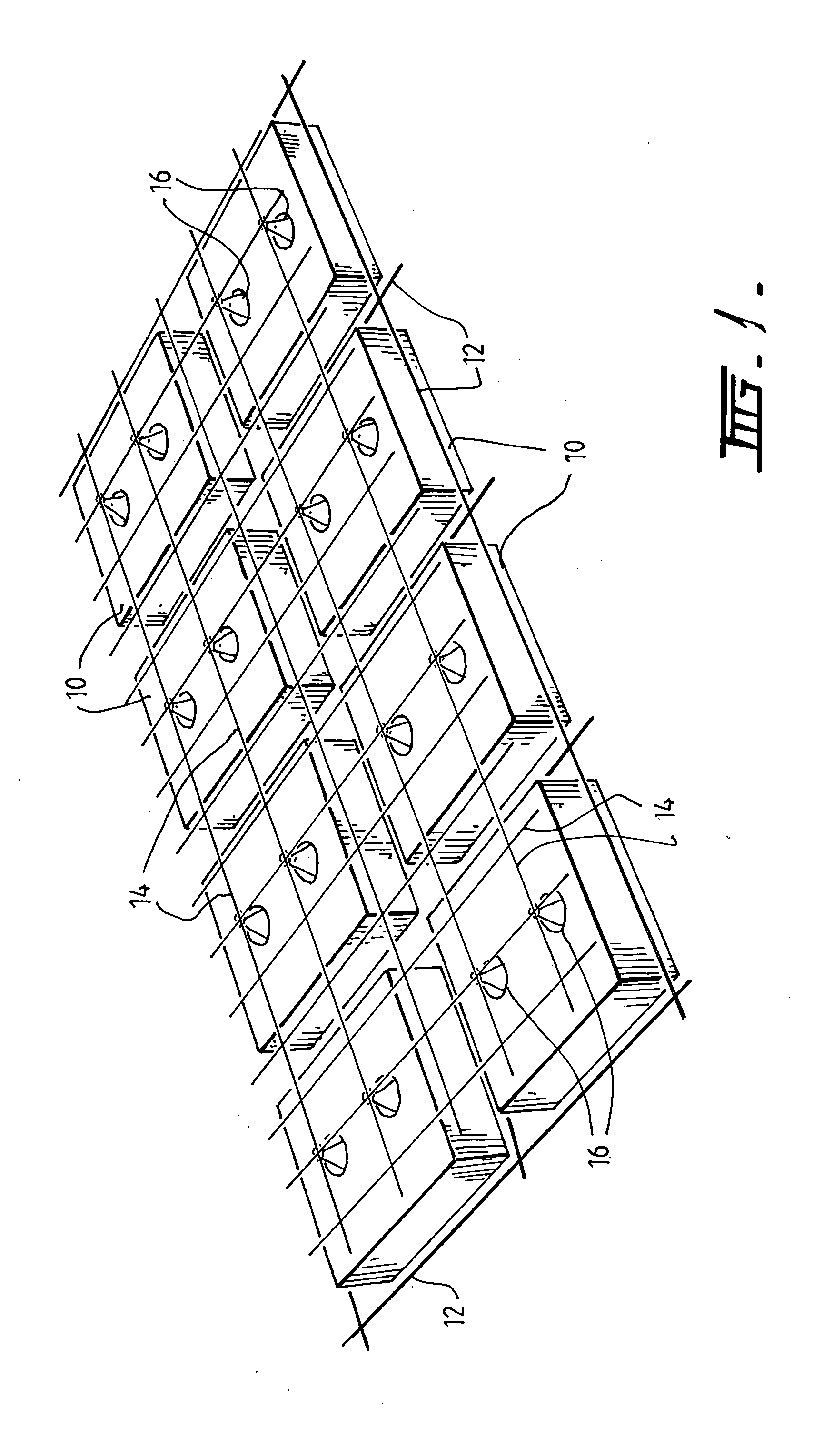
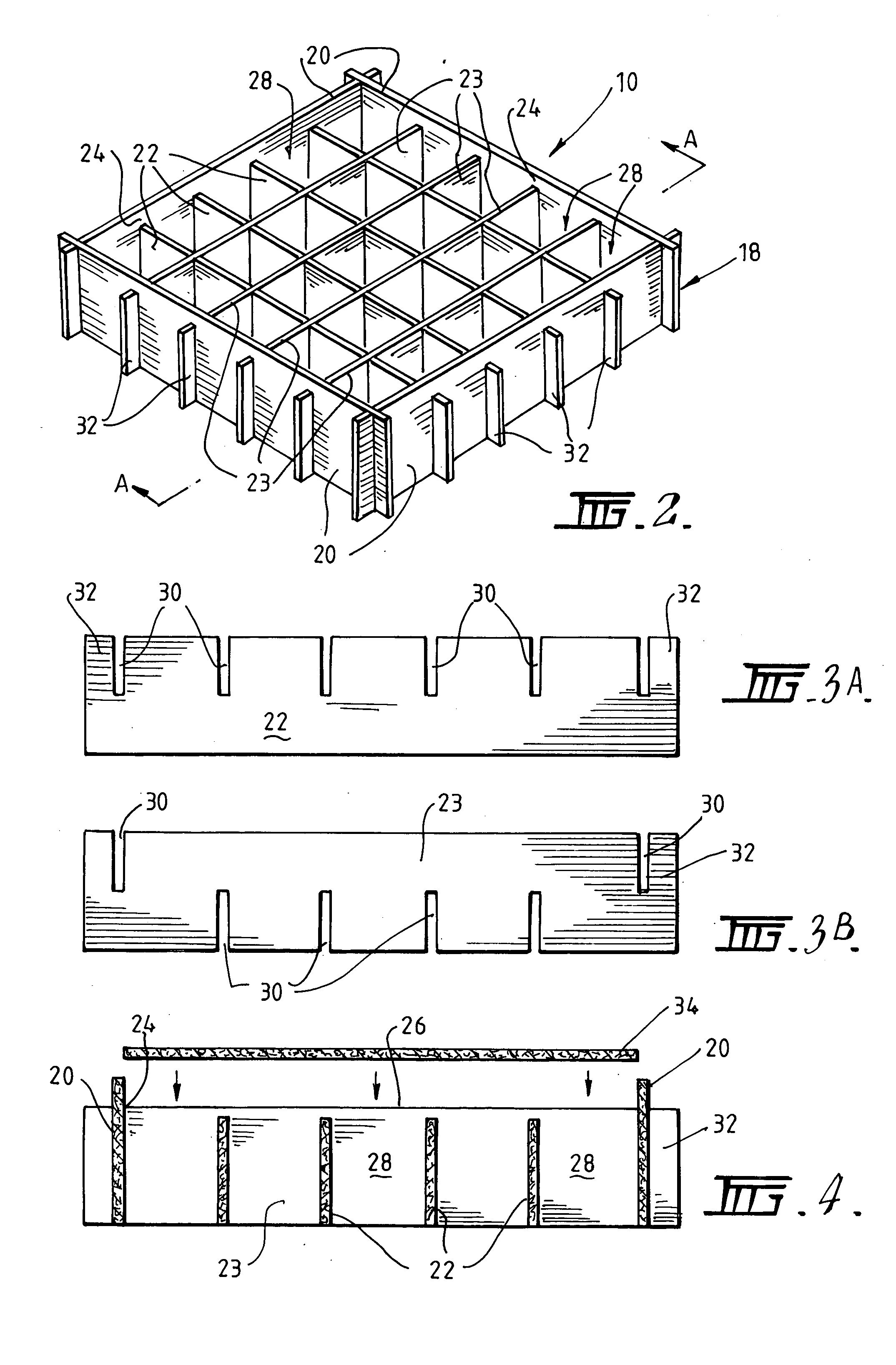
[0054] Referring to cavity former 10 illustrated in FIGS. 2 to 5, it can be seen that the base 18 of the cavity former 10 has a support member comprising an array of elements in the form of panels 22 and 23 for supporting the weight of wet concrete until it is sufficiently cured to support itself, and a rim 24 formed on the peripheral panels 20 which operates to locate and retain the cover means on the panels 22 and 23. The cover means is provided in the form of a lid 34 (FIG. 4). It will, therefore, be appreciated that the weight of wet concrete on the lid 34 will be distributed to the panels 22, 23 along their upper edges.

[0055] The panels 20, 22 and 23 are preferably formed from a degradable material, which disintegrates over time to leave a cavity within the slab. The panels 20, 22 and 23 may otherwise be formed from any material having the required strength to support the weight of a worker standing on the cavity former or of the wet concrete poured to form the slab.

[0056] Whi...

second embodiment

[0064] Reference is now made to a second embodiment illustrated in FIGS. 6A, 6B and 7, in which like parts are indicated by like numerals preceded by a 1. Cavity former 110 comprises a base 118 and a cover means in the form of a lid 134. The base 118 has end walls 40 and support elements 42 located between the end panels 40. The support panels 42 are formed from a number of sections 46 joined via fold lines 44 to enable the support panels to expand and contract in length in a concertina-type effect. As can be seen from FIG. 7, the contraction of the support panels 42 enables the base 118 to collapse to a reduced volume for conveniently transporting the cavity formers 110. The support panels 42 have a bias toward the collapsed state.

[0065] The lid 134 in FIG. 6A comprises a panel 56, in the shape of a square, having opposed depending side walls 54. The cavity former 110 is formed by moving the end walls 40 apart to configure the base 118 into an expanded state thereby allowing the li...

third embodiment

[0067] the present invention is illustrated in FIGS. 8 and 9. in which like parts are indicated with the numerals preceded by a 2. As shown in FIG. 8, the cavity former 210 comprises a base 218 to which may be fitted the lid 134 in FIG. 6A.

[0068] The base 218 comprises end walls 62 and intermediate support panels 64 all of which are generally parallel and connected at their respective ends by a pair of flexible webs 66. Furthermore, the upper edges 62 of the end walls 60 are spaced above the upper edges 68 of the support panels 64 by an amount equal to the thickness of the plate 56 of the lid 134.

[0069] The base 218 can be re-configured into a collapsed state as depicted in FIG. 9 by moving each adjacent panel closer to its neighbour such that there is substantially no space between the panels 60 and 64. In this configuration, the base218 has a substantially reduced volume relative to the expanded state shown in FIG. 8 and thereby enables the base 218 to be more conveniently transp...


PUM

PropertyMeasurementUnit
Timeaaaaaaaaaa
Pressureaaaaaaaaaa
Lattice constantaaaaaaaaaa

Abstract

A cavity former 10 for use in forming a cavity in a concrete slab is disclosed. The cavity former comprises a support member which supports the weight of a person standing on the cavity former or of wet concrete bearing down on the array until the concrete has cured sufficiently to support itself. The array is reconfigurable between a compact state for stacking with other similarly configured arrays to facilitate transport and an expanded state to define a volume about which the wet concrete is poured. The cavity former 10 has a cover 34 which is engageable with the array to distribute the weight onto the array elements and prevent wet concrete flowing into the volume defined by the elements in the expanded state.

Description

CROSS-REFERENCE TO RELATED APPLICATIONS [0001] This application claims the benefit of Australian patent application serial no. 2003903688, filed Jul. 16, 2003. The disclosure of the above application is incorporated herein by reference. FIELD OF THE INVENTION [0002] This invention relates to concrete slabs and foundations. More specifically, the invention relates to an apparatus for forming a hollow cavity in a slab or foundation. BACKGROUND OF THE INVENTION [0003] The practice of using cavity formers as space filling members in the preparation of a concrete slab or foundation is an existing technique for reducing the amount of concrete required to form a slab or foundation. While the reduced concrete content in a slab having hollow cavities serves to reduce the cost of the slab, it also advantageously allows the slab to be built on unstable soil as expanding soils will flow into the formed cavities. Such cavities also assist the easy placement of electrical and plumbing conduits th...

Claims


Application Information

Patent Timeline
IPC IPC(8): B28B7/34E04G9/08E04G15/06
CPCB28B7/342B28B23/0068E04B5/36E04G15/061E04G9/08E04G9/086E04G9/021
Inventor O'GRADY, JAMES FRANCISDONALD, LIGE GILBET
Owner AUSTRALIAN STEEL OPERATIONS THE
Why Eureka
Try Eureka