
Musical instrument transducer

Inactive Publication Date: 2005-01-20
FISHMAN TRANSDUCERS
View PDF19 Cites 24 Cited by
  • Summary
  • Abstract
  • Description
  • Claims
  • Application Information

AI Technical Summary

Benefits of technology

[0007] In a preferred embodiment, the presently disclosed transducer assembly is configured to contain four piezoelectric transducer disks arrayed in a circle, inside an enclosure that has the outer shape of a bass violin bridge height adjuster. The enclosure is composed of a cylindrical base with a threaded post, and a cover with a non-threaded cylindrical post. The base and cover are mechanically and electrically joined with an electrically conductive adhesive to ensure good electromagnetic shielding continuity when the enclosure is grounded. Within the enclosure, an interior or bottom surface of the cover is in physical contact with the piezoelectric transducer disks. Thus, the ground path extends from the upper surface of the transducer disks through the cover, the electrically conductive adhesive, and the base to a cable connected thereto. The transducer disks themselves are mounted on a disk of copper-clad circuit board with an electrically conductive adhesive to complete the electrical path between the bottom of the transducer disks, across the metalized circuit board, and to a conductor of a connected cable. A rigid, electrically isolating spacer is disposed between the transducer disks. This disk assembly sits on a resilient, insulating support inside the enclosure. A center conductor of a coaxial cable makes contact with the copper-clad portion of the circuit board, and an outer shield of the cable makes contact with the enclosure. The cable is terminated in this preferred embodiment at a jack-plug pair to allow quick disconnection and reconnection when the enclosure is rotated, thereby preventing tangling or damage to the cable.
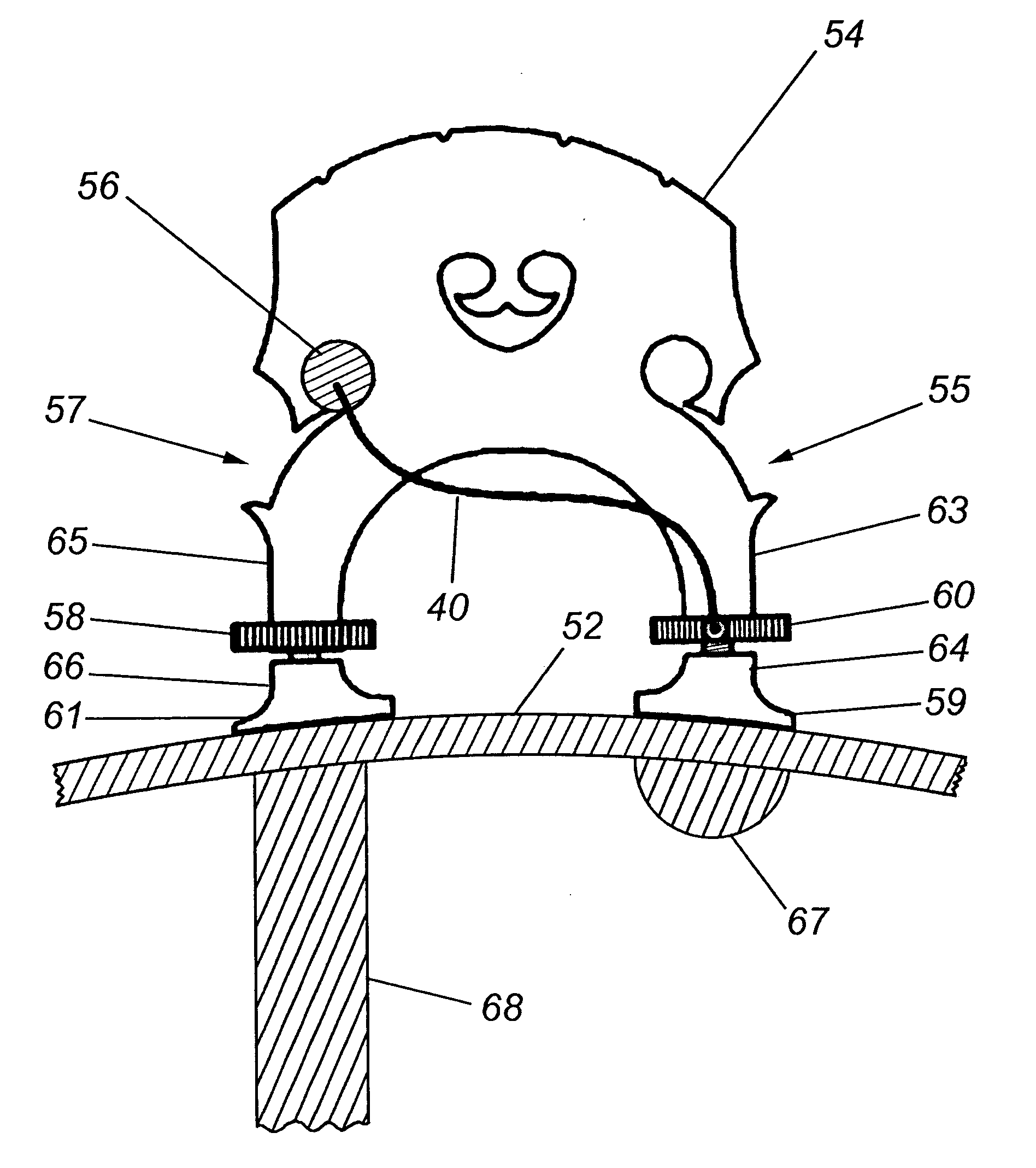
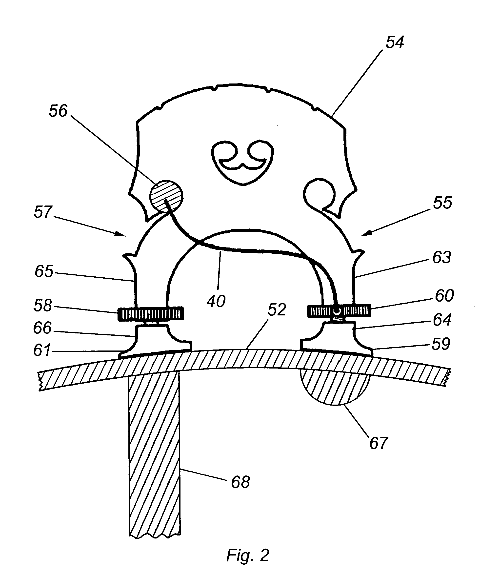
[0009] Inside the body of a bass violin, there are two particular structures below the legs of the bridge. Under the treble leg there is a support known as a sound post, mechanically connecting the top and back parts of the body of the instrument. Under the bass leg, attached to the inside of the top part of the body, there is a longitudinal rib called the bass bar, a structural support that is also used to tune the response of the instrument. The rigidity of the sound post and the relative flexibility of the bass bar cause the bridge to effectively pivot around the sound post in response to the motion of the strings. Thus there is a major advantage to installing a force sensing mechanism in the bass leg of the bridge, where there is a much greater mechanical excursion. Bowing and plucking the strings of an instrument with this bridge support configuration will each give different modes of vibration.
[0011] Additionally in the preferred embodiment, the resilient support is made of a material such as silicone rubber selected for a combination of thickness and durometer that distributes pressure evenly on the transducer disks and prevents over-clamping due to extreme height adjustment, thus preserving the dynamic range of the transducers. The resiliency of the material results in a self-aligning support which further limits the effects of over-clamping and serves to keep the transducers in an optimal range of clamping forces for maximum response. A typical combination would be a thickness in the range of 0.020″ to 0.040″, with a durometer in the range of 40 to 60 Shore A.

Problems solved by technology

This style of transducer allows good reproduction of the sound of plucked strings, but is deficient at reproducing the sound of bowed strings.
Another drawback includes the risk of the transducer being dislodged and possibly damaged with handling or while in transit.
This style of construction leaves both the piezoelectric elements and their cable connections exposed and vulnerable to damage.

Method used


Image

  • Musical instrument transducer
  • Musical instrument transducer
  • Musical instrument transducer

Examples


Embodiment Construction

[0021] A musical instrument transducer of the force sensing transducer type is disclosed and shown mounted in the leg of the bridge of a bass violin.

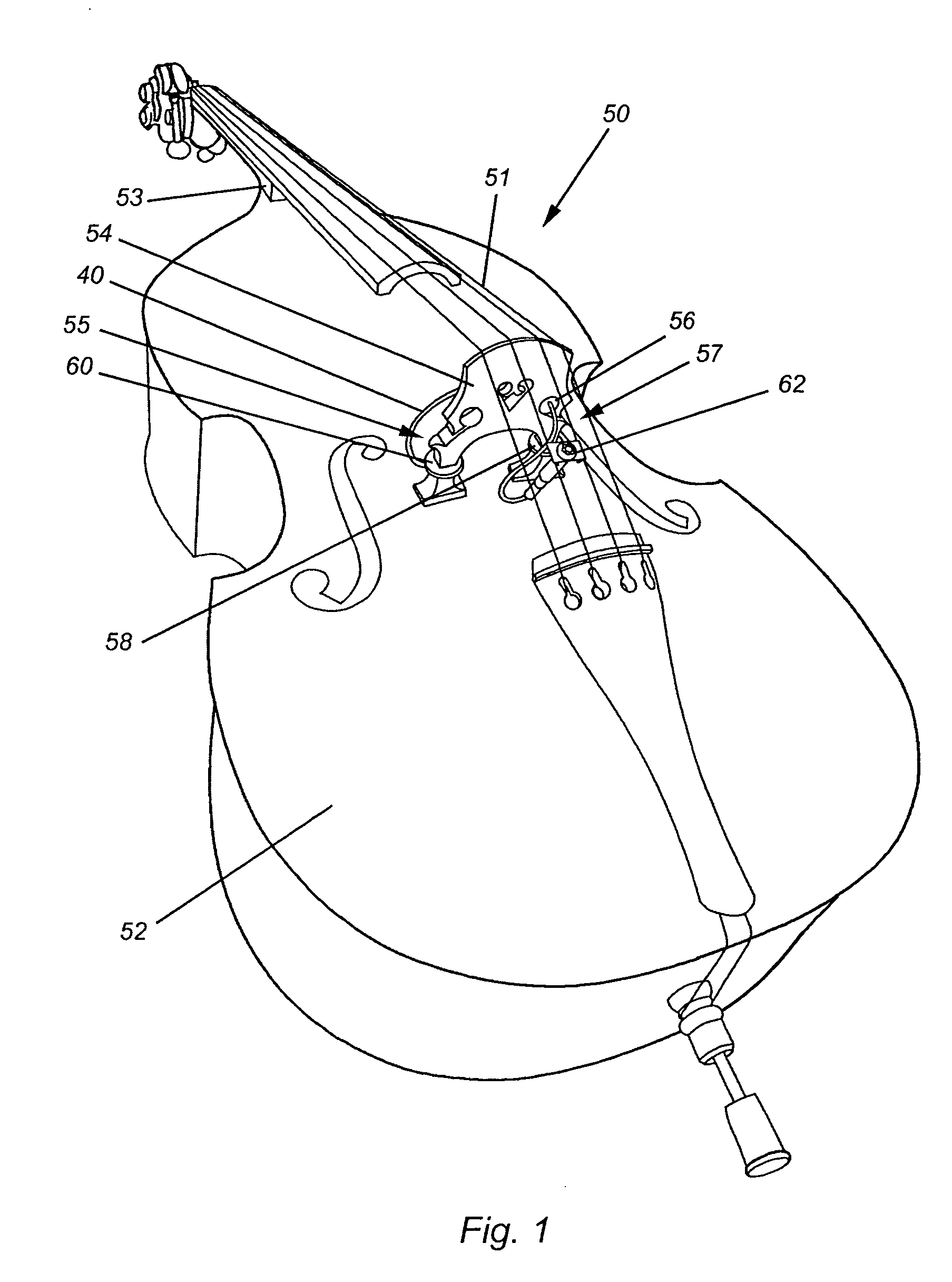
[0022] As described above, in a preferred embodiment, there is shown in FIG. 1 a stringed musical instrument in the form of a bass violin 50 comprising a body 52, a neck 53, a bridge 54, and a plurality of strings 51. Mounted in the bass leg 55 of the bridge 54 is a force sensing transducer 60, and mounted in the treble leg 57 of the bridge 54 is a commonly available height adjuster 58. Further shown is a coaxial cable 40 electrically connecting the force sensing transducer 60 to the jack and plug assembly 62, and a foam rubber or neoprene isolation plug 56 that secures the coaxial cable 40 relative to the bridge 54.

[0023] A more detailed view of the mounting scheme of a presently preferred embodiment is shown in FIG. 2, including the location of both the bass bar 67 and the sound post 68. FIG. 3 depicts the unplugged jack subassembly...


PUM


Abstract

A plurality of force sensing transducer elements are enclosed in a stringed musical instrument bridge height adjuster, designed to be installed as one of a pair of height adjusters in the legs of the bridge. The transducers are disposed to allow rotation of the adjuster to control how the modes of vibration in the bridge affect the transducers, thus allowing the player to adjust the tonal response of the transducers to the instrument and to their own sound preference. An inline jack-plug pair allows the output cable of the transducer to be quickly disconnected and reconnected to avoid straining or tangling the cable while adjusting the tone and the bridge height.

Description

FIELD OF THE INVENTION [0001] The present invention relates generally to musical instrument transducers for use with stringed musical instruments employing a bridge for a portion of their string support. More particularly, the invention pertains to a stringed instrument such as a bass violin. STATEMENT REGARDING FEDERALLY SPONSORED RESEARCH OR DEVELOPMENT [0002] N / A BACKGROUND OF THE INVENTION [0003] There are numerous musical instrument transducers in existence, and several of them have been designed specifically in an attempt to solve the problem of producing an accurate electrical replica of the sound of an instrument such as a bass violin. A conventional musical instrument transducer of the force sensing transducer type for use with a bass violin is disclosed in U.S. Pat. No. 4,356,754 issued Nov. 2, 1982 and entitled Musical Instrument Transducer. The conventional transducer described herein has a plurality of piezoelectric elements attached with clips onto one of the faces of ...

Claims


Application Information

Patent Timeline
IPC IPC(8): G10H3/14G10H3/18
CPCG10H3/143G10H3/183G10H2220/565G10H2220/471G10H2220/525G10H3/185
Inventor FISHMAN, LAWRENCE R.
Owner FISHMAN TRANSDUCERS
Learn More