
Detonator identification and timing assignment

a technology of detonators and timing assignments, applied in the field of blasting systems, can solve problems such as fatigue of personnel, mistakes, and difficulty in establishing a blasting system in an underground environment, and achieve the effect of limiting the effects of noise and stray signals

Active Publication Date: 2016-07-07
DETNET SOUTH AFRICA (PTY) LTD
View PDF3 Cites 8 Cited by
  • Summary
  • Abstract
  • Description
  • Claims
  • Application Information

AI Technical Summary

Benefits of technology

The patent is about identifying a signal that helps to locate a detonator in a borehole. The identifying signal can be in the form of ultraviolet, infrared, or optical waves and is designed to be unique and resistant to interference. The source of the signal can be a continuous, intermittent, or pulsed source, and can be coded to identify the specific detonator. The identifying signal can be modulated in different ways to accurately identify the connector. The technical effect of this technology is to provide a reliable and accurate way to locate detonators in a borehole, which can improve the accuracy and efficiency of drilling operations.

Problems solved by technology

The establishing of a blasting system in an underground environment can be problematic for, usually, arduous conditions prevail.
Skilled personnel should be used to establish the blasting system but, even so, such personnel may become fatigued and make mistakes.

Method used


Image

  • Detonator identification and timing assignment
  • Detonator identification and timing assignment
  • Detonator identification and timing assignment

Examples


Embodiment Construction

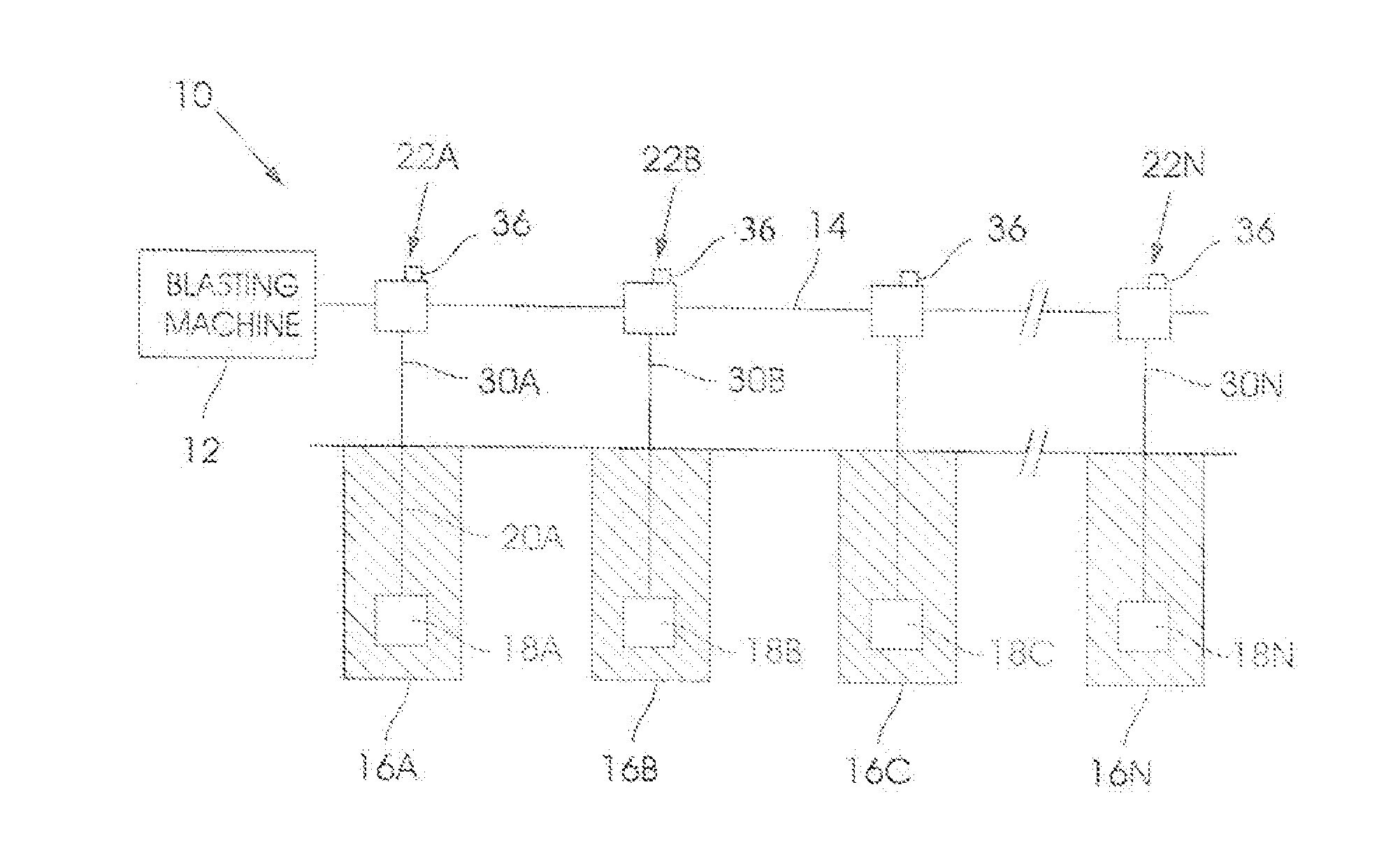
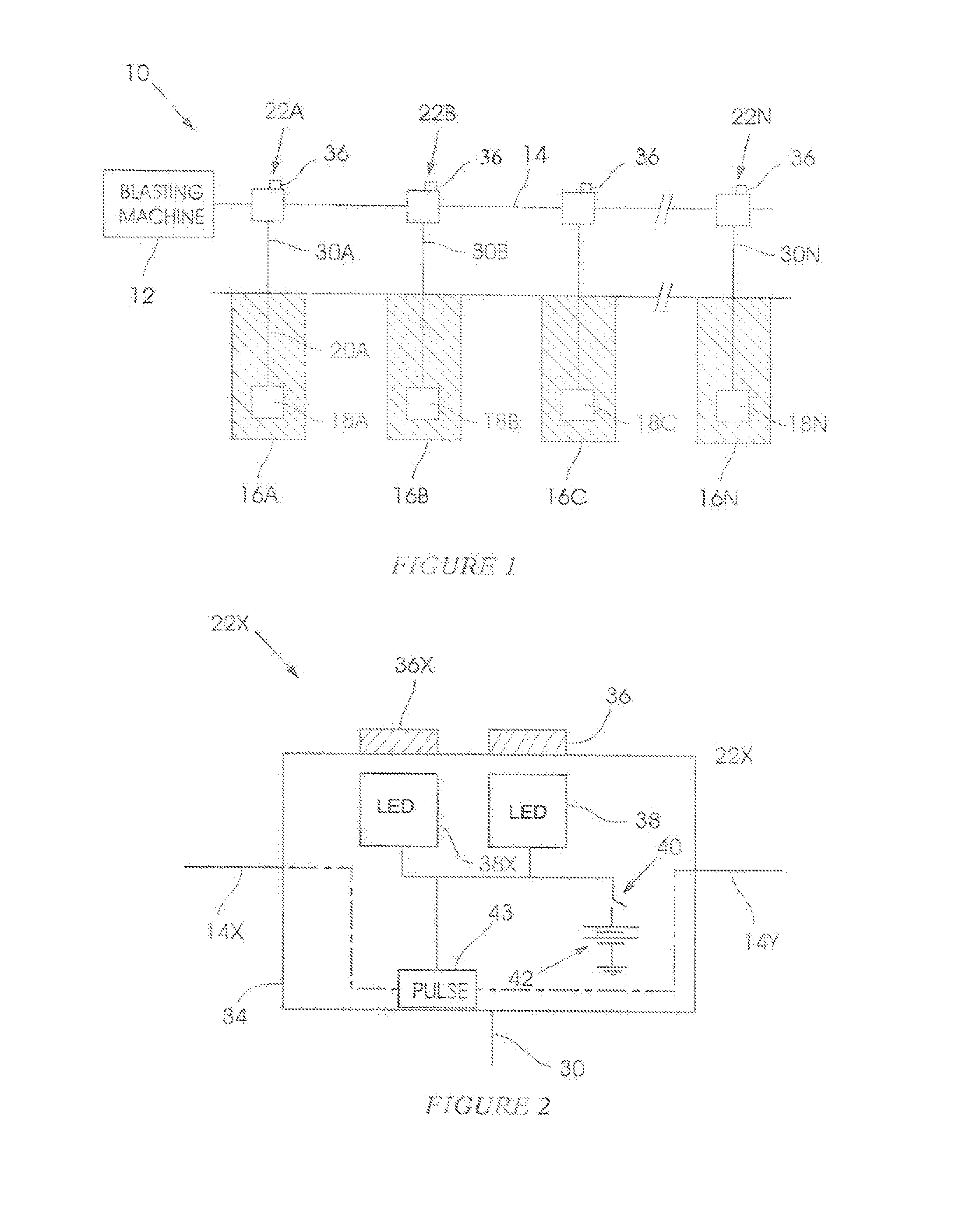
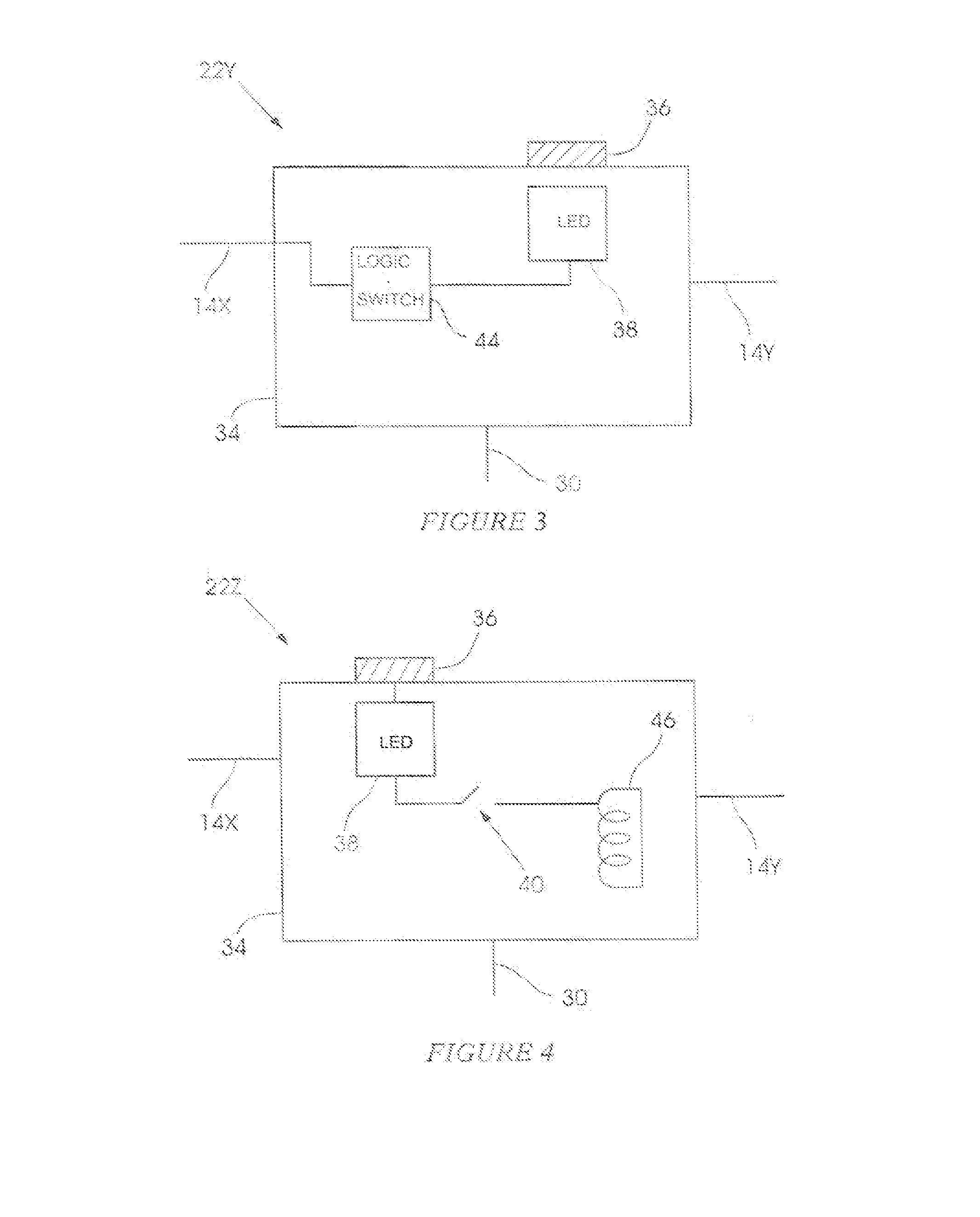
[0028]FIG. 1 of the accompanying drawings illustrates a blasting system 10 which includes a blasting machine 12, of any suitable type, an elongate harness 14, a plurality of boreholes 16A, 16B, 16C . . . 16N, a plurality of detonators 18A, 18B . . . 18N which are respectively located in the boreholes and which are exposed to respective explosive charges 20A to 20N, and a plurality of connectors 22A, 22B . . . 22N which are respectively used to connect the detonators 18A to 18N to the harness 14.

[0029]Although the principles of the invention find particular application in an underground location, this application is exemplary and non-limiting. The principles of the invention are described hereinafter with particular reference to the implementation thereof using signals in a visible frequency range. This is exemplary only and non-limiting for signals which lie in other ranges e.g. infrared or ultraviolet, may be used, as appropriate. The choice of the frequency of the identifying sign...


PUM


Abstract

A device for use in a blasting system which Includes a plurality of detonators, wherein the device Includes a connector for making a connection between the detonator and a harness in the blasting system, wherein the connector includes a housing and at least one Identifying source on the housing operable to emit an identifying signal thereby to Identify the physical location of the housing.

Description

BACKGROUND OF THE INVENTION[0001]This invention relates generally to a blasting system and more particularly is concerned with identifying a physical location of a detonator in a blasting system and assigning accurate timing data to the detonator.[0002]The establishing of a blasting system in an underground environment can be problematic for, usually, arduous conditions prevail. Once blast holes have been drilled and prepared, detonators must be loaded into the respective blast holes and interconnected to a blasting machine. Correct timing sequences must be assigned to the detonators. Skilled personnel should be used to establish the blasting system but, even so, such personnel may become fatigued and make mistakes.[0003]An object of the present invention is to address, at least to some extent, the aforementioned situation.SUMMARY OF THE INVENTION[0004]The invention provides, in the first instance, a device for use in a blasting system which includes a plurality of detonators, where...

Claims


Application Information

Patent Timeline
Patent Type & Authority Applications(United States)
IPC IPC(8): F42D5/02F42D1/055
CPCF42D5/02F42D1/055C06C7/00F42C11/06F42D1/05
Inventor VAN WYK, RIAAN
Owner DETNET SOUTH AFRICA (PTY) LTD
Learn More