Locomotive draft gear assembly and yoke

a technology of gear assembly and locomotive, which is applied in the direction of railcar coupling accessories, draw-gear, railway components, etc., can solve the problems of increasing the speed difference between the railcars, severe impact on the coupler of the awaiting car, and increasing the impact of buff and draft on the couplers, so as to achieve the effect of light weigh

Inactive Publication Date: 2005-01-20
AMSTED RAIL CO INC
View PDF7 Cites 18 Cited by
  • Summary
  • Abstract
  • Description
  • Claims
  • Application Information

AI Technical Summary

Benefits of technology

[0010] It is another object of the present invention to provide an improved, lighter weight locomotive draft gear assembly.

Problems solved by technology

Yard impact events include “humping” of the individual cars to build the train in the yard; in humping, a car is pushed over a hump in the track in the yard, released and allowed to roll down the incline of the hump toward an awaiting car; during humping, the released cars can reach speeds of 4-10 mph and can severely impact the coupler of the awaiting car.
As a result of the slack being progressively taken up, the speed differences between the railcars increases as the slack at each coupler pair is taken up, with a resultant increase in buff and draft impacts on the couplers.
The slack in the last coupler pair is taken up very rapidly and the last two cars are subjected to a very large impact capable of damaging the lading or the car.

Method used


Image

  • Locomotive draft gear assembly and yoke
  • Locomotive draft gear assembly and yoke
  • Locomotive draft gear assembly and yoke

Examples


Embodiment Construction

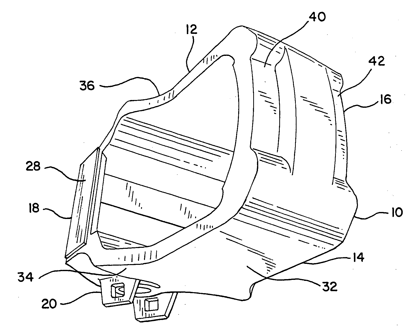
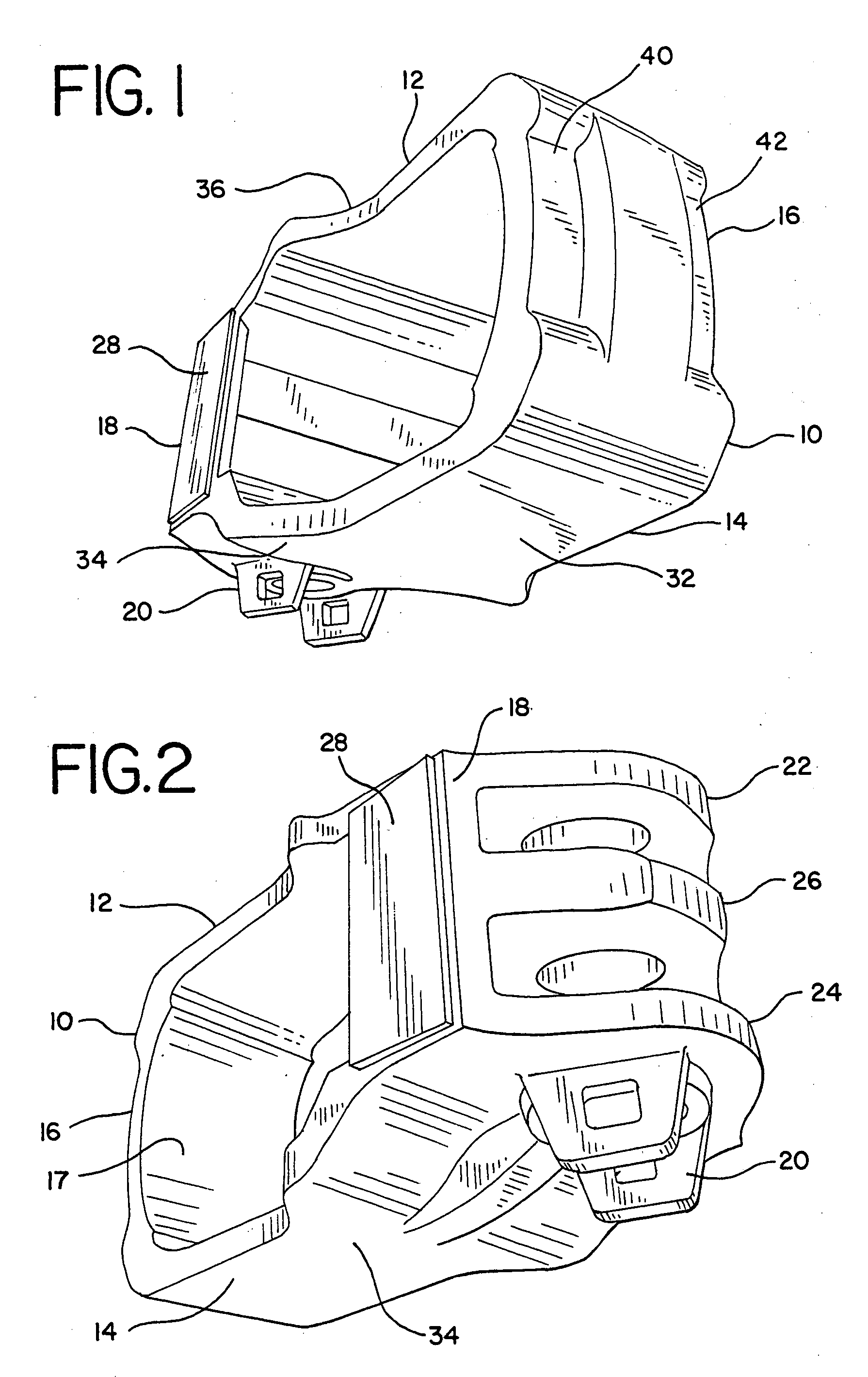
[0019] Referring now to FIGS. 1 and 2 of the drawings, a yoke for use in a locomotive draft gear assembly is shown generally at 10. Such yoke is typically a single casting of steel. Yoke 10 is seen to comprise an elongated top strap 12 and an elongated bottom strap 14. Rear end 16 of yoke 10 and front end 18 of yoke 10 are joined by top strap 12 and bottom strap 14.

[0020] Back wall 16 is shown as having an inner concave surface 17 adapted to abut against the complementary convex surface of the rear follower.

[0021] Front wall 18 is seen to comprise two side sections 28 that are spaced laterally and extend from top strap 12 to bottom strap 14. Front wall is further seen to comprise a top section 22, center section 26, and bottom section 24. Each of front wall top section 22, front wall center section 26 and front wall bottom section 24 are seen to have a convex edge extending from a center forward most portion back into contact with front wall side sections 28. A draft pin retainer ...


PUM


Abstract

A yoke for use in a railway locomotive draft gear assembly is provided. The yoke includes a back wall, a front wall and top and bottom straps that extend from the front wall to the back wall. The front wall includes two side sections and a bottom section and a top section. The top strap and bottom strap are tapered to a reduced width at the back wall. The draft gear assembly includes the yoke with a coupler follower adjacent the front wall of the yoke and a rear follower adjacent the back wall of the yoke. A resilient member is located between the followers.

Description

BACKGROUND OF THE INVENTION [0001] The present invention relates to railcar coupling systems, and more particularly to draft gear assemblies used in conjunction with draft sills and couplers in locomotives. [0002] Draft gear assemblies form the connection between the couplers at the ends of adjoining railroad freight cars and the draft sills at the ends of the freight cars. The draft sills are commonly cast or fabricated sills that are mounted at the ends of the center sills of the railcar. The draft sills have a pair of front stops and a pair of rear stops, with a draft gear pocket between the stops. The draft gear assembly is received in the draft gear pocket. [0003] Each draft gear assembly is connected to one coupler, and couplers of adjacent rail cars are connected to form the train. The train may be one hundred cars long and drawn by one or more locomotives. Typically, there is a limited amount of slack or free movement allowed between the cars; generally there is about two in...

Claims


Application Information

Patent Timeline
Patent Type & Authority Applications(United States)
IPC IPC(8): B61G7/00B61G9/22
CPCB61G9/22B61G7/00
Inventor FETTEROLF, JOHN F.CLARK, MARLIN E.SMITH, ALLEN D.
Owner AMSTED RAIL CO INC
Why Eureka
Try Eureka