
Extendable segmented sample carrier system

a sampling system and segmented technology, applied in the field of sample carrier systems, can solve the problems of confusion as to the identity of any given carrier, difficulty in identifying certain specimens, and separate risk of errors in maintaining an identifying order, so as to achieve more reliable sample test results, reduce errors, and save time

Inactive Publication Date: 2005-01-20
BECKMAN COULTER INC
View PDF18 Cites 24 Cited by
  • Summary
  • Abstract
  • Description
  • Claims
  • Application Information

AI Technical Summary

Benefits of technology

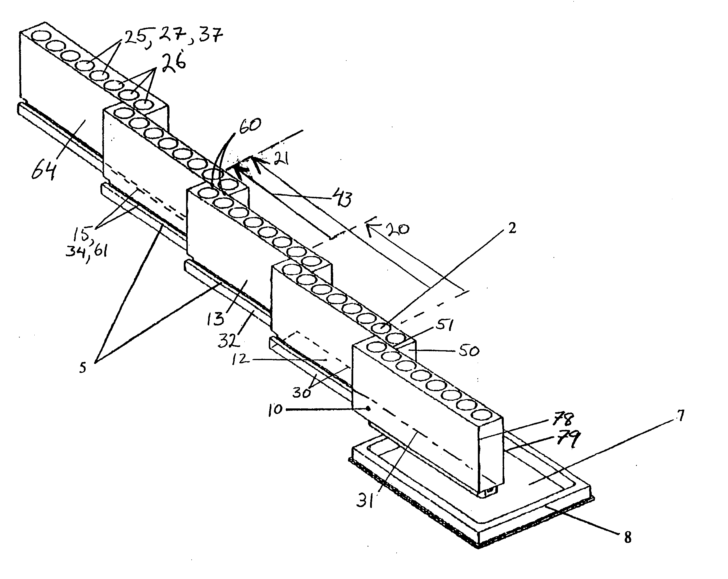
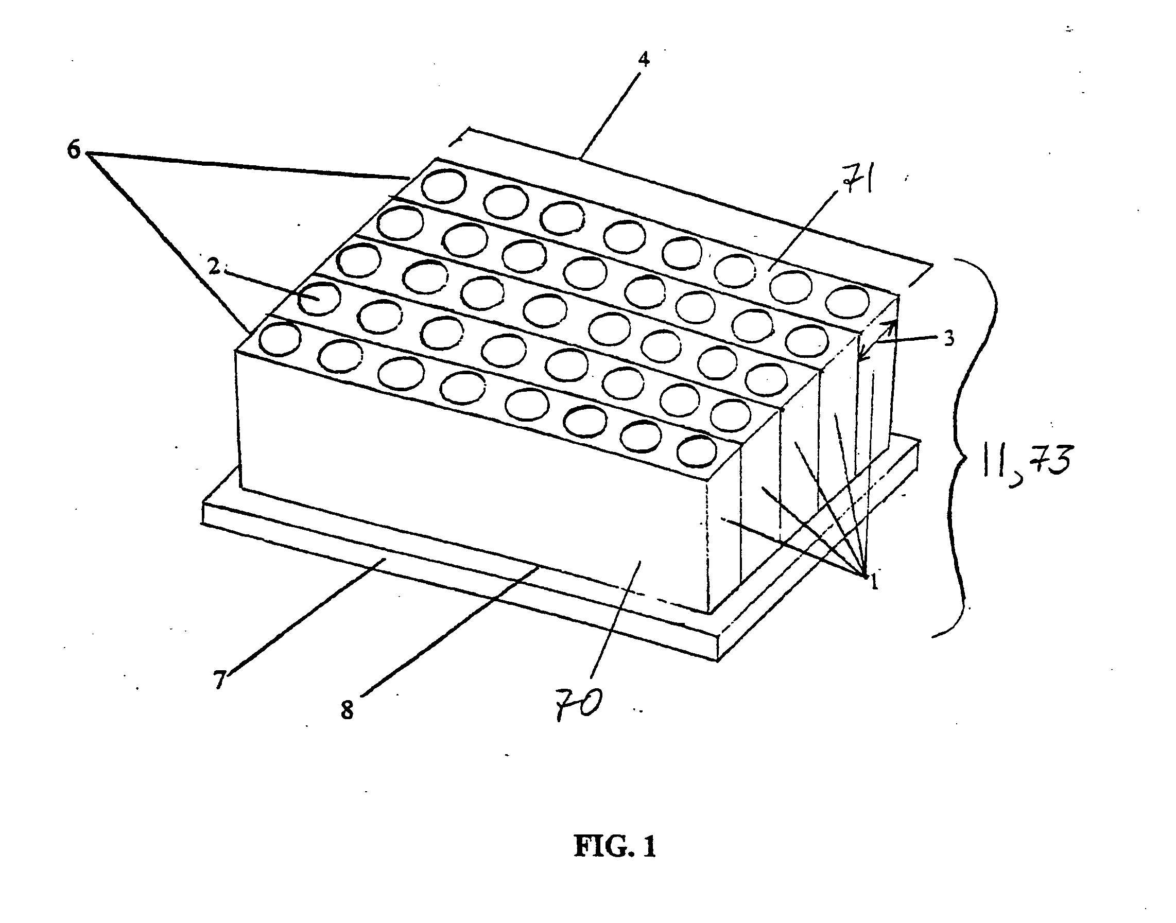
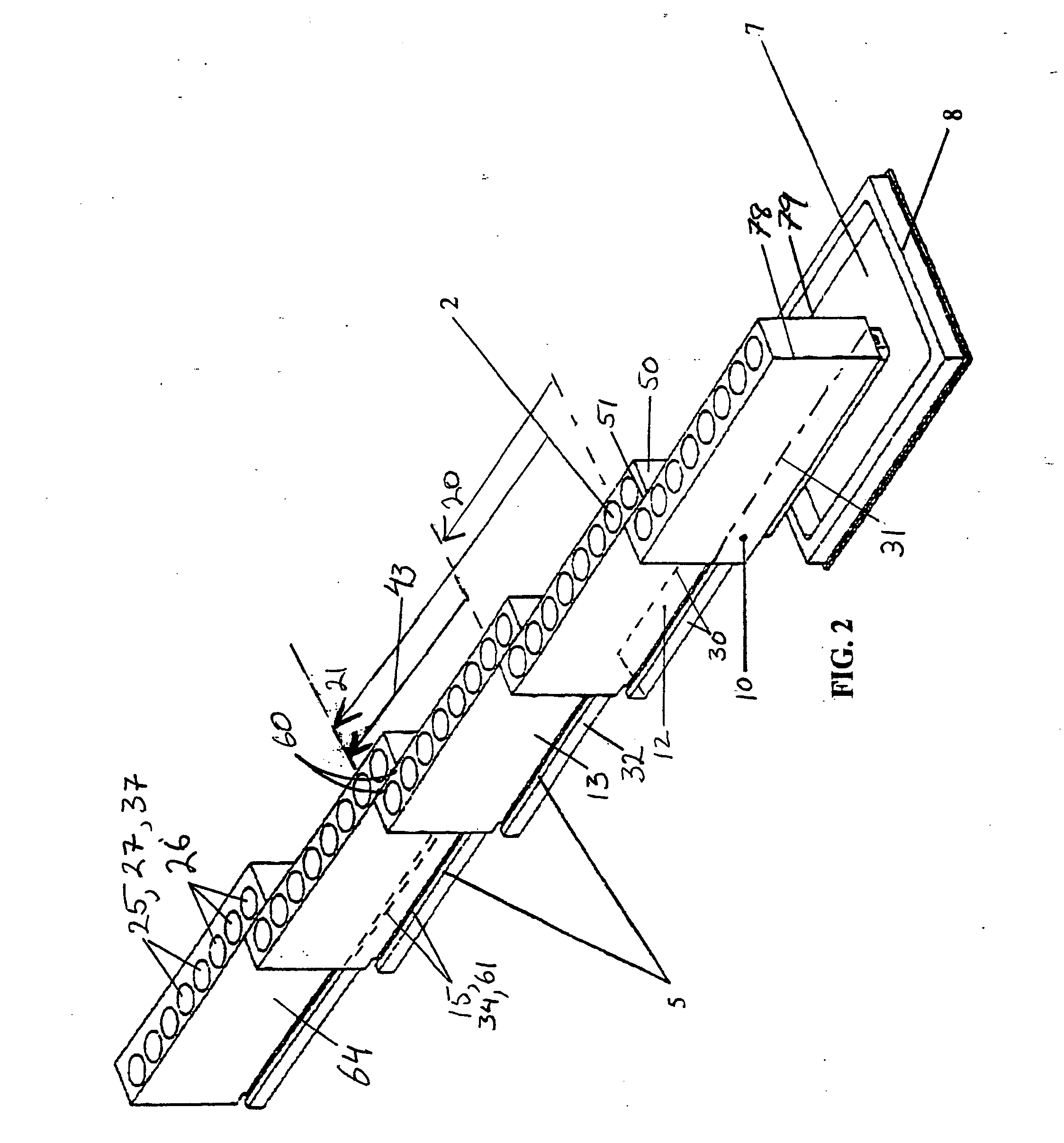
[0008] Generally, this invention relates to an extendably reconfigurable sample carrier containment system or sample retention apparatus for and methods of securing sample carriers such as test tubes, cuvettes and the like, or samples, in an orderly matrix fashion and providing for a rearrangement into a substantially linear fashion without requiring the translocation of individual specimen carriers, thereby saving time, reducing errors and providing for more reliable sample test results.
[0009] Rearrangement of a plurality of similar appearing specimen carriers such as, for example, test tubes, from a planar row-by-row fashion into a substantially linear fashion is often desired by individuals performing tests on contained substances because such individuals find that a substantially linear presentation (or more generally, a presentation that is other than row-by-row) of similar appearing items is less likely to result in individual item identification errors than is a row-by-row presentation of items. The substantially linear arrangement of sample carriers, in presenting sample carriers such as test tubes substantially in only one dimension, allows for easier handling of an individual sample or sample carrier (such as physically retrieving a carrier from or placing a carrier into a certain receptacle) and easier and less error-prone manipulation of the contained substance (such as adding a reagent to a contained substance or removing a portion of a substance from its carrier). The present invention may be configured in two stable opposite modalities or configurations (in addition to other intermediate modalities which may be included under the term “extended”)—one is compacted (or retracted), in which receptacles for holding sample carriers such as test tubes, or the samples themselves, may be presented for use in a row-by-row, matrix type arrangement that is common among commercially available microtitre plates. The retracted modality of the present invention may include a tray for holding and securing in its compacted form the receptacle housings, or more generally, the sample retention housing elements. Another, opposite modality of the invention is fully extended, in which the specimen carrier receptacles, or more generally, sample retention elements, may be presented in a substantially linear form as part of a plurality of receptacle housing rows or sample retention housing elements, each of which may have only one side of one (e.g., 50) or both ends positioned adjacent and perhaps in physical contact with (or close to) a side of an end of a different sample retention housing element. Reconfiguration from the compacted (or retracted) to the extended (whether fully extended or not) modality may be provided for by reconfiguration elements such as a slideably coupled, interlocked track and runner device that engages adjacent receptacle housing segments or adjacent sample retention housing elements. The housing, and a tray in which the housing may securely rest, may be sized such that the device, in its compacted form, may readily interface with loading systems of specimen processing equipment, by, for example, fitting into receptacles for microtitre plates that may exist as part of an autoclave or centrifuge.
[0010] It is a goal of this invention to provide a more accurate testing process by eliminating the step of translocation of individual specimen carriers, while still providing (a) the advantages offered by a standard matrix type microtitre arrangement (such as compatibility with different pieces of equipment used for sample determination such as an autoclave or centrifuge that are designed to operate on matrix type microtitre plates of certain size), and (b) the capability of (re)arrangement into a less error prone, substantially linear arrangement. The elimination of the step of translocation of individual specimen carriers into a less error-prone substantially linear arrangement results in a specimen testing process that is inherently more accurate, that provides test results in which scientists and other users of the test data can be more confident, and, simply, is faster.
[0011] It is a goal of the present invention to achieve a higher sample carrier density (higher is defined relative to typical commercially available matrix-type microtitre plates), thereby enabling the inclusion of more contained samples per, for example, autoclave run, and effecting cost savings (and a saving of time that might otherwise be spent loading and unloading individual specimen carriers). This higher density (or closer proximity of one receptacle or sample retention element to another) can be achieved because the present invention, with its reconfiguration capability, eliminates the obstruction effect presented by rows of carriers without requiring relocation of any individual carriers, thereby enabling easier manipulation and handling of any single individual specimen carrier. Such a higher density sample retention apparatus may referred to as a sample retention element density enhanced sample retention apparatus.

Problems solved by technology

Oftentimes, when a plurality of samples have discrete containment in a matrix type arrangement (as used herein, the term matrix type plate, or microtitre plate, is used to refer to a row-by-row arranged sample carrier holder), the close proximity of the carriers as secured in the receptacles, or integral to the carrier itself, makes their individual removal (and placement into a specific holding receptacle), or specific location difficult and may also cause confusion as to the identity of any given carrier or the contents contained within.
Difficulty in identifying certain specimens within the discrete sample carriers may also stem from the repetitive row-by-row arrangement of identically appearing carriers that may be found in a typical matrix type plate.
However, the process of rearranging the contained samples into a less-error prone arrangement itself introduces a separate risk of errors in maintaining an identifying order among the carriers.
Even if no errors are actually made, the simple act of rearrangement may cause insecurity on the part of the individual who uses the carriers in their reconfigured arrangement as to the exact identity of each carrier (and insecurity on the part of the user of the resulting test data).
As rearrangement of samples from typical containment systems (such as commercially available microtitre plates) into an simplified order (for example, linear) requires individual samples (and their carriers) be moved about (translocated) and perhaps also that the order of samples be repeatedly changed, errors in marking and recording, or switching of samples become extremely difficult to police.
Another, separate problem posed by existing test tube or other specimen carrier containment systems also stems from the difficulty in handling carriers such as test tubes that are arranged in a row-by-row fashion.
Due to the simple fact that the closer the test tubes (or other sample carriers) are located to one another in a matrix type microtitre plate, the more difficult handling of the carrier or handling of the sample is, existing matrix type plates often limit the carrier holding receptacle per plate surface area density.

Method used


Image

  • Extendable segmented sample carrier system
  • Extendable segmented sample carrier system
  • Extendable segmented sample carrier system

Examples


Embodiment Construction

[0018] The device (FIGS. 1 & 2 show one embodiment), which may be generally referred to as a sample retention apparatus (11), may comprise a plurality of receptacle housing elements or more generally, sample retention housing elements (1), the outer edges of each of which may be substantially rectangular in horizontal cross-sectional area. The apparatus may be segmented and thus comprise a first (10), second (12) and a third (13) sample retention housing element. The term “first sample retention housing element” may be viewed as a relatively arbitrary label used to refer to a sample retention housing element that is on either exterior side of the apparatus (70, 71). When the apparatus is in a retracted configuration (see FIG. 1), the second sample retention housing element may be situated proximate to (or more specifically alongside (see FIG. 1)) the first sample retention housing element, and the third sample retention housing element may be situated proximate to (or more specifica...


PUM


Abstract

A sample carrier system (1) with spatially adjustable configuration provides variable positioning as to the relative location of a plurality of sample containment elements (1). In a preferred embodiment, a slidably reconfigurable sampling system in which a matrix type, row-by-row arrangement of receptacles or sample retention elements (1) for specimen carriers such as cuvettes, test tubes and beakers, or the like (40), or for samples (41), may be reconfigured into a substantially linear arrangement of individual specimen carriers along with the entrained material contents, providing more accurate testing processes and more reliable test results.

Description

CROSS-REFERENCES TO RELATED APPLICATIONS [0001] This application claims the benefit of U.S. Provisional Application 60 / 338,957, filed Dec. 7, 2001, entitled “Extendable Segmented Sample Carrier System” and hereby incorporated by reference.BACKGROUND OF THE INVENTION [0002] A sample carrier system or apparatus with spatially adjustable reconfiguration provides variable positioning as to the relative location of a plurality of sample retention elements. Specifically, a slidably reconfigurable sampling system in which a matrix type, row-by-row arrangement of receptacles for sample carriers such as cuvettes, test tubes and beakers, or the like, or samples themselves, may be reconfigured into a substantially linear arrangement of individual specimen carriers along with any entrained material contents. [0003] In clinical laboratory work, such as sample assaying, it may be common to have a large number of different samples that are each contained in a discrete cuvette, test tube, beaker or...

Claims


Application Information

Patent Timeline
IPC IPC(8): B01L3/00B01L9/00B01L9/06G01N35/04
CPCB01L3/50855B01L9/06B01L9/523G01N35/026B01L2200/022B01L2300/0829G01N2035/0427B01L9/54B01L1/52
Inventor BUCHANAN, KRISTOPHER S.FOX, NATHAN M.BAHJAT, KEITH S.
Owner BECKMAN COULTER INC
Learn More