Disposable, sterile fluid transfer device

a sterile fluid and dispensing technology, applied in the direction of liquid handling, catheters, packaging goods, etc., can solve the problems of increasing the risk of contamination of the entire system, not always possible, and using steam

Inactive Publication Date: 2005-01-27
MILLIPORE CORP
View PDF99 Cites 97 Cited by
  • Summary
  • Abstract
  • Description
  • Claims
  • Application Information

AI Technical Summary

Benefits of technology

[0011] The downstream components are assembled to the device and it is placed in the closed position. The entire device and downstream components are sterilized, such as with gamma radiation. In use the device and downstream components are attached by the face to the upstream compone

Problems solved by technology

It would be desirable to have a completely sealed system but this is not always possible with the processes that take place in production.
Several disadvantages exist with the use of steam.
This increases the risk of contamination of the entire system.
Also the high temperatures and pressure differentials of the steam make the selection of filter materials and components very difficult and limited and even then an accidental pressure differential at high temperatures can cause a fil

Method used


Image

  • Disposable, sterile fluid transfer device
  • Disposable, sterile fluid transfer device
  • Disposable, sterile fluid transfer device

Examples


Embodiment Construction

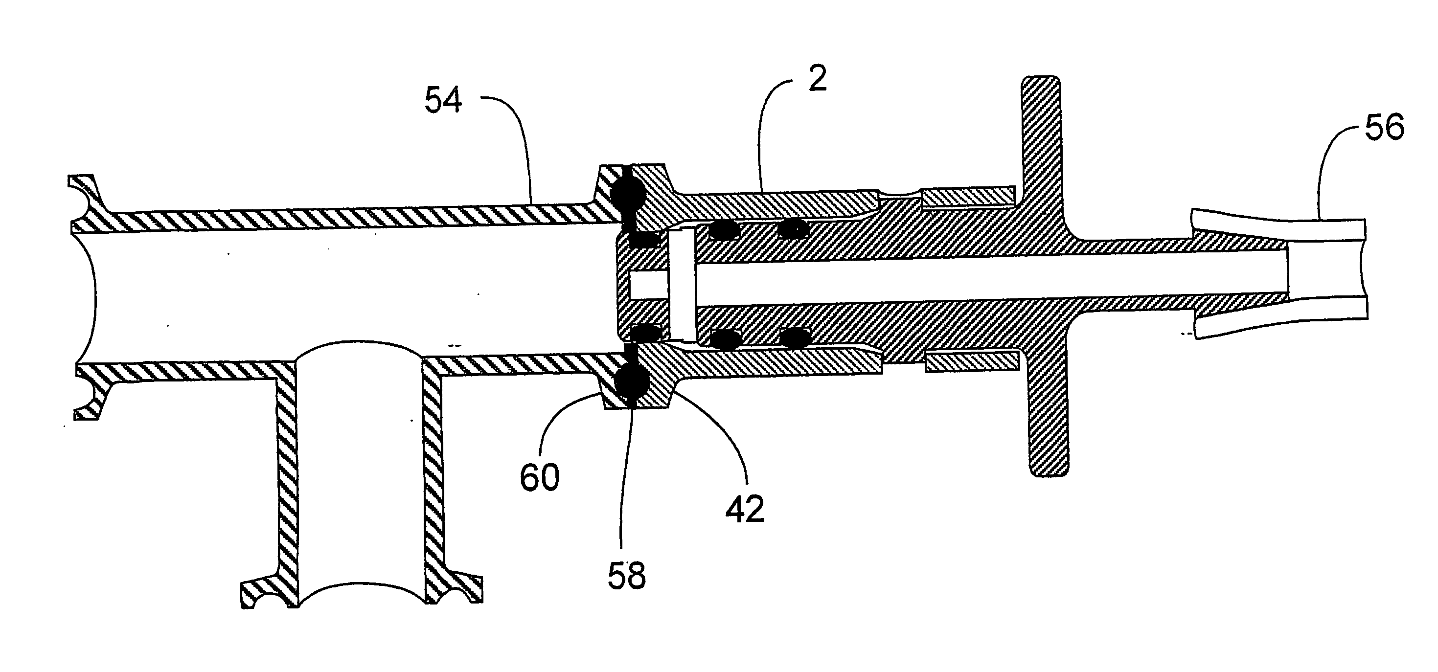
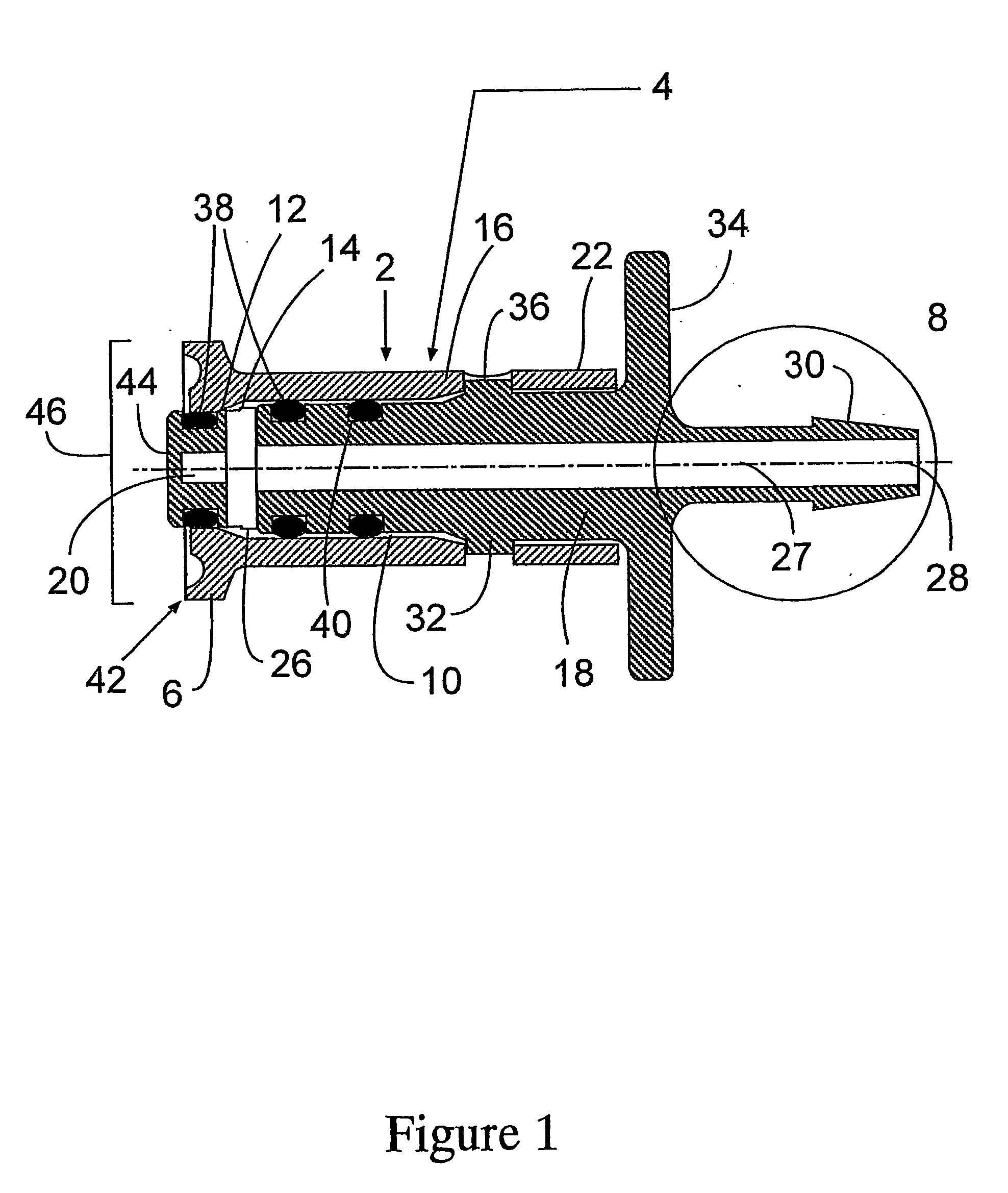
[0037] The present invention is a sterile fluid transfer device, preferably in the form of a connector or a valve.

[0038] A first embodiment of the present invention is shown in FIG. 1. The device 2 is formed of a body 4 having a first end 6 and a second end 8. The body 4 also has a bore 10 extending in this embodiment from the first end 6 to the second end 8. The bore 10 as shown is formed of three sections each with a different diameter. There is the first bore section 12 which has a first set diameter, a transition bore section and a second bore section which has a second set diameter that is greater than the first set diameter of the first bore section 12. The transition bore section 14 is arranged between the first and second bore sections 12, 16 and has an outwardly tapering diameter along its length with the diameter of the transition section 14 adjacent the first bore section 12 being equal to the first set diameter and the diameter of the transition section 14 adjacent the ...


PUM

PropertyMeasurementUnit
Lengthaaaaaaaaaa
Electrical resistanceaaaaaaaaaa

Abstract

The present invention relates to a sterile transfer device for fluids, be they liquids or gases. It is comprised of a body having a bore formed through at least a portion of its interior. Preferably, it is a central bore formed through the entire length of the body. Contained within the bore is a movable plunger. The body has a first and a second end. The first end contains a face designed to be attached to the upstream component. The second end is connected to a downstream component such as a filter, pipeline, sample bag and the like. The plunger has corresponding first and second ends. The first end of the plunger when it the closed position is in alignment with the face of the body which combined form a steamable surface and a sterile barrier against the environment to the rest of the interior of the body, the plunger and downstream components.

Description

[0001] The present invention relates to a disposable, sterile fluid transfer device. More particularly, it relates to a disposable sterile fluid transfer device, preferably in the form of a connector or valve for use in the pharmaceutical and biopharmaceutical industry. BACKGROUND OF THE INVENTION [0002] In the pharmaceutical, biotechnology and even food, beverage and cosmetics industries, it is often desired to provide a processing system that is capable of handling fluids in a sterile manner. This is designed to prevent unwanted, often dangerous organisms, such as bacteria as well as environmental contaminants, such as dust, dirt and the like from entering into the process stream and / or end product. It would be desirable to have a completely sealed system but this is not always possible with the processes that take place in production. [0003] There is a need for the introduction or removal of materials from the process stream in order to add components of the product, such as medi...

Claims


Application Information

Patent Timeline
IPC IPC(8): A61M39/10B67D99/00A61M39/16A61M39/18A61M39/22F16K3/26F16K15/18F16K17/40F16L37/107
CPCA61M39/10A61M39/16A61M39/18A61M39/22A61M2039/1027F16K5/00F16K3/265F16K13/04F16K15/18F16L37/107A61M2039/222
Inventor PROULX, STEPHENALMASIAN, JOSEPHRENGANATH, NARENTINGLEY, STEPHENMORRISSEY, MARTIN
Owner MILLIPORE CORP
Why Eureka
Try Eureka