

Method and apparatus for bonding polarizing plate
a technology of polarizing plate and apparatus, which is applied in the direction of polarizing elements, instruments, other domestic objects, etc., can solve the problems of reducing yield, unable to be reloaded or transported with an acceptable operating convenience, and inability to shorten the time, so as to achieve the effect of prohibiting stop marks and easy exercise of control of the direction of the axis of light transmission of the polarizing pla
- Summary
- Abstract
- Description
- Claims
- Application Information
AI Technical Summary
Benefits of technology
Problems solved by technology
Method used
Image

Examples
an embodiment 2 (
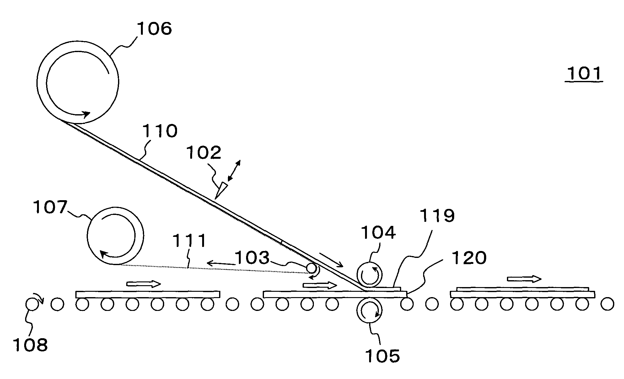
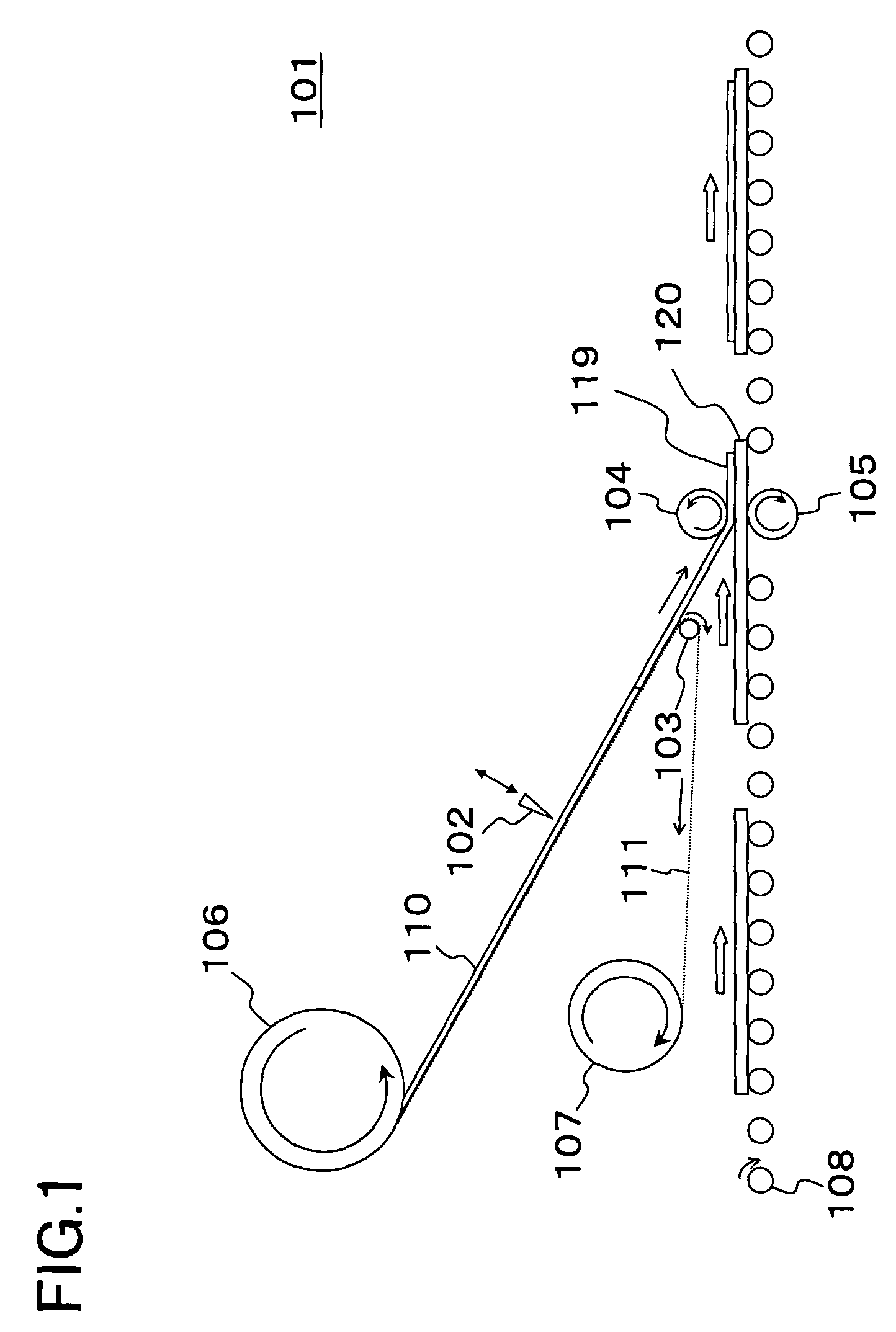
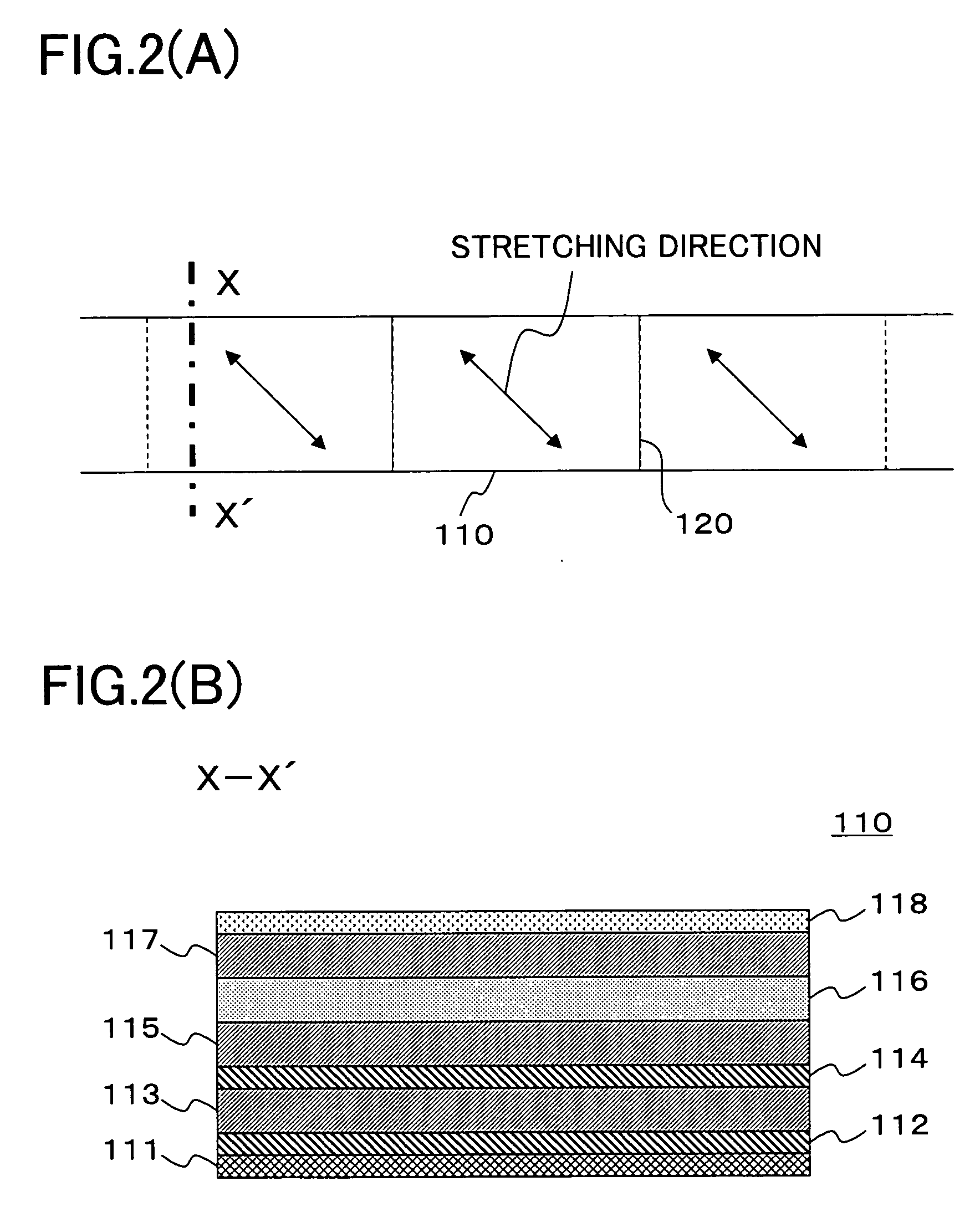
second solution) is now explained with reference to the drawings. FIG. 18 is a side view schematically illustrating the structure of a polarizing plate bonding apparatus. FIG. 19 is a developed perspective view schematically illustrating the relationship between a substrate and stretching directions of polarizing plates bonded to both substrate surfaces by the polarizing plate bonding apparatus according to embodiment 1 of the present invention (second solution).
Referring to FIG. 18, a polarizing plate bonding apparatus 240 according to embodiment 2 of the second solution includes a first release film separating means 241A, a second release film separating means 241B, a bonding means 242 and a cutting means 243. The first release film separating means 241A separates a release film 211A from a first strip-shaped film 210A, which is composed of a polarizing plate and the release film 211A bonded thereto with interposition of an adhesive layer, and which is supplied from the front sid...
embodiment 4
of the present invention (second solution) is now explained with reference to the drawings. FIG. 24 is a side view schematically showing the structure of a first transport unit of a polarizing plate bonding apparatus of the present invention (second solution). FIG. 25 is a side view schematically showing the structure of a second transport unit of the polarizing plate bonding apparatus according to embodiment 4 of the present invention (second solution).
Similarly to the polarizing plate bonding apparatus according to embodiment 3 of the second solution, shown in FIG. 20, the polarizing plate bonding apparatus of embodiment 4 of the second solution is roughly divided into a first transport unit, an inverting unit and a second transport unit. In the first transport unit, a substrate (201A of FIG. 21), supplied from a supply unit, is transported, a polarizing plate reeled out from a reel-out roll is separated from a release film, and the polarizing plate is bonded to the lower side o...
embodiment 3
of the present invention (third solution) is explained with reference to the drawings. FIG. 31 is a side view schematically showing the structure of a polarizing plate bonding apparatus of the present invention (third solution).
A polarizing plate bonding apparatus 340 according to embodiment 3 of the third solution is substantially similar in structure to the polarizing plate bonding apparatus according to embodiment 1 of the third solution except the mounting positions of a release film separating means 341, reel-out roll 344 and takeup roll 345. This polarizing plate bonding apparatus 340 includes, below the substrate 301 transported on transporting means 346, the release film separating means 341, reel-out roll 344 and takeup roll 345. By supplying the strip-shaped film 310 from the lower side of the plate surface of the substrate 301 to be transported, and by having the strip-shaped film 310 bonded in position, it is possible to prevent intrusion of contaminants as well as to ...
PUM
| Property | Measurement | Unit |
|---|---|---|
| Linear density | aaaaa | aaaaa |
| Thickness | aaaaa | aaaaa |
| Thickness | aaaaa | aaaaa |
Abstract
Description
Claims
Application Information