Electromagnetic suspension system

a technology of electromagnetic suspension and lateral force, applied in the field of shock absorbers, can solve the problems of reducing electromagnetic force and power consumption, preventing smooth operation requiring undesirable increase in size and weight of the extensible member, so as to reduce the effect of lateral for

Active Publication Date: 2005-01-27
HITACHI ASTEMO LTD
View PDF15 Cites 25 Cited by
  • Summary
  • Abstract
  • Description
  • Claims
  • Application Information

AI Technical Summary

Benefits of technology

[0008] The present invention provides an electromagnetic suspension system comprising: an extensible member including a cylinder and a rod capable of displacement relative to the cylinder; a first cylindrical member connected to the rod, either one of a coil member and a magnetic member being provided in the first cylindrical member; and a second cylindrical member provided in such a manner as to permit radial movement thereof relative to the cylinder while preventing axial movement thereof relative to the cylinder, the other of the coil member and the magnetic member being provided in the second cylindrical member, the second cylindrical member facing either one of an inner side and an outer side of the first cylindrical member. In this electromagnetic suspension system, if a lateral force acts on the extensible member, the lateral force does not have any significant effect on the second cylindrical member, with respect to radial or rocking movement thereof. Therefore, excessive sliding friction does not occur in slide / support members for the first and second cylindrical members, thus ensuring smooth axial relative displacement between the first and second cylindrical members.
[0009] The present invention also provides an electromagnetic suspension system comprising: an extensible member including a cylinder and a rod capable of displacement relative to the cylinder; a second cylindrical member connected to the cylinder, either one of a coil member and a magnetic member being provided in the second cylindrical member; and a first cylindrical member provided in such a manner as to permit radial movement thereof relative to the rod while preventing axial movement thereof relative to the rod, the other of the coil member and the magnetic member being provided in the first cylindrical member, the first cylindrical member facing either one of an inner side and an outer side of the second cylindrical member. In this electromagnetic suspension system, if a lateral force acts on the extensible member, the lateral force does not have any significant effect on the first cylindrical member, with respect to radial (rocking) movement thereof. Therefore, excessive sliding friction does not occur in slide / support members for the first and second cylindrical members, thus ensuring smooth axial relative displacement between the first and second cylindrical members.
[0010] The present invention further provides an electromagnetic suspension system comprising: an extensible member including a cylinder and a rod capable of displacement relative to the cylinder; a second cylindrical member provided in such a manner as to permit radial movement thereof relative to the cylinder while preventing axial movement thereof relative to the cylinder, either one of a coil member and a magnetic member being provided in the second cylindrical member; and a first cylindrical member provided in such a manner as to permit radial movement thereof relative to the rod while preventing axial movement thereof relative to the rod, the other of the coil member and the magnetic member being provided in the first cylindrical member, the first cylindrical member facing either one of an inner side and an outer side of the second cylindrical member. In this electromagnetic suspension system, the second cylindrical member is capable of radial movement relative to the cylinder and the first cylindrical member is capable of radial movement relative to the rod. Therefore, it is possible to minimize an effect of a lateral force acting on the extensible member with respect to the first and second cylindrical members.

Problems solved by technology

(1) One of the cylindrical members strongly presses the other, so that sliding resistance is generated between the magnet and the coil respectively provided in the cylindrical members, thus preventing smooth operation of the extensible member.
(2) If a space between the magnet and the coil is radially increased to avoid the above problem (1), a gap between the magnet and the coil increases, so that a lowering of an electromagnetic force and an increase in power consumption occur.
(3) If the extensible member is imparted with an increased stiffness to solve the above problem (1), an undesirable increase in the size and the weight of the extensible member is necessary.

Method used


Image

  • Electromagnetic suspension system
  • Electromagnetic suspension system
  • Electromagnetic suspension system

Examples


first embodiment

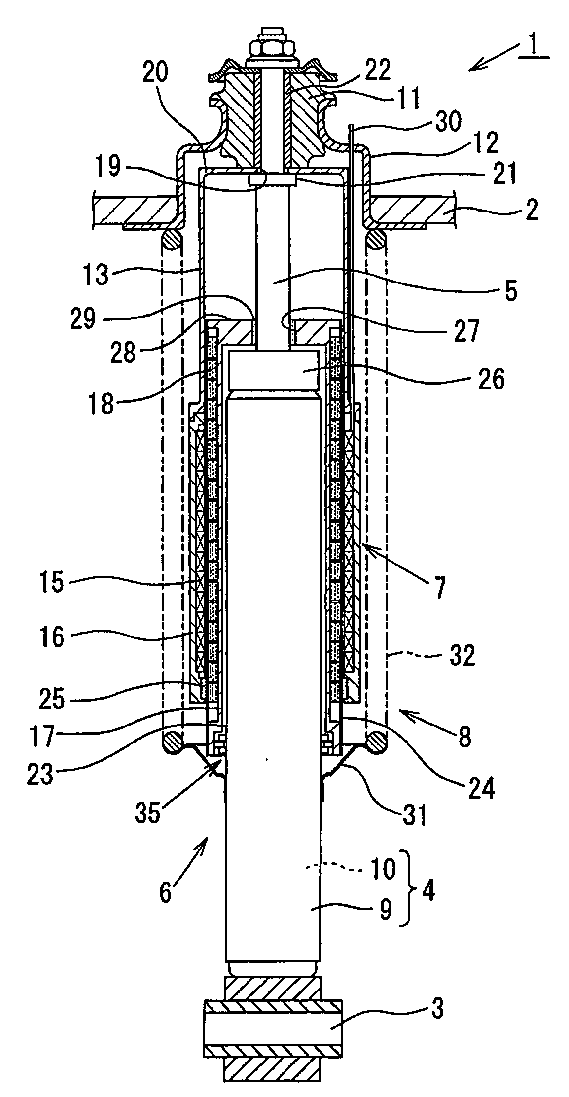
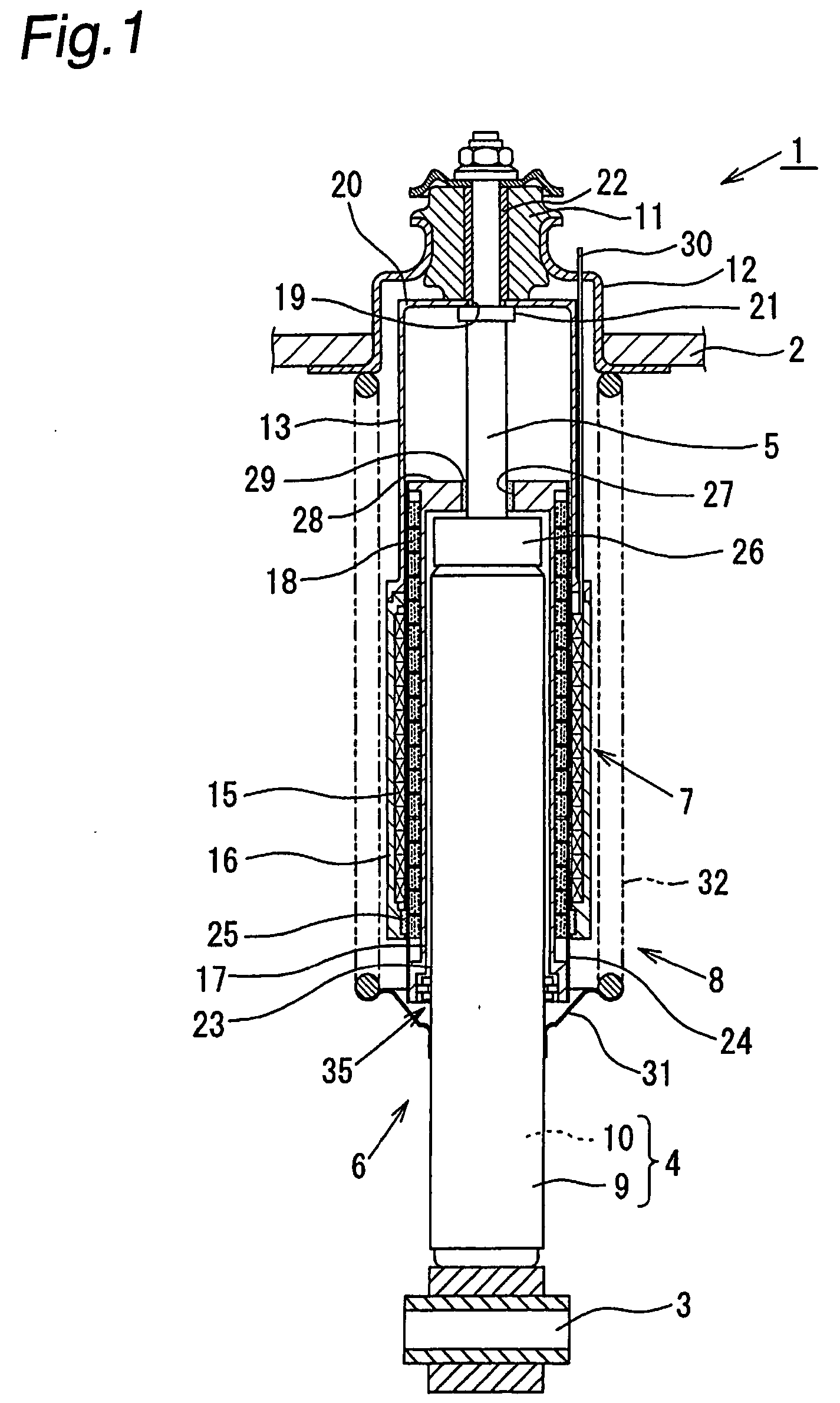
[0034] Referring to FIGS. 1 and 2, description is made with regard to an electromagnetic suspension system according to the present invention. In FIG. 1, an electromagnetic suspension system 1 is provided between a vehicle body 2 and an axle 3 of a vehicle. The electromagnetic suspension system 1 comprises a hydraulic damper 6 (or a shock absorber) as an extensible member, an electromagnetic linear motor 7 and a spring mechanism 8.

[0035] The hydraulic damper 6 comprises a cylinder 4 and a piston rod 5 capable of displacement relative to the cylinder 4.

[0036] The cylinder 4 has a dual-tube structure comprising an outer tube 9 and an inner tube 10.

[0037] One end of the piston rod 5 is attached to a piston (not shown). The piston is slidably disposed within the inner tube 10, thus dividing the inside of the inner tube 10 into two liquid chambers. The other end of the piston rod 5 is connected through a rubber bush (hereinafter referred to as “the vehicle-body rubber bush”) 11 to an u...

fourth embodiment

[0078] Next, referring to FIG. 8, description is made with regard to an electromagnetic suspension system 1C according to the present invention. The same members as indicated in FIG. 1 are designated by the same reference numerals as used in FIG. 1, and explanation thereof is omitted.

[0079] As shown in FIG. 8, the electromagnetic suspension system 1C comprises a universal joint mechanism 35E provided between the center-yoke cover portion 28 of the center yoke 17 and the cap 26. The universal joint mechanism 35E comprises a plurality of openings 68 formed in the center-yoke cover portion 28, which are arranged in a circumferential direction about the opening 27 of the center-yoke cover portion 28, and pins (cap-fixing pins) 69 inserted into the openings 68. The cap-fixing pin 69 comprises a pin body 70 which is extended through the opening 68 and fixed to the cap 26 and a pin head 71 fixed to the pin body 70. The pin head 71 of the cap-fixing pin 69 abuts against an outer surface of ...

fifth embodiment

[0081] Next, referring to FIG. 9, description is made with regard to an electromagnetic suspension system 1a1 according to the present invention. The same members as shown in FIG. 1 are designated by the same reference numerals as used in FIG. 1, and explanation thereof is omitted.

[0082] The electromagnetic suspension system 1a1 comprises the cap 26 (corresponding to a rod guide) connected to the outer tube 9. A rod guide 26a integral with the cap 26 is provided inside the cap 26. A dry metal (hereinafter referred to as “the in-cap dry metal”) 29a is provided inside the rod guide 26a, so as to guide sliding movement of the piston rod 5.

[0083] A ring member 80 (corresponding to a spherical bearing) is connected to the cap 26 and the outer tube 9. The ring member 80 extends between a portion of the cap 26 on a side of the outer tube 9 and a portion of the outer tube 9 on a side of the cap 26. The ring member 80 generally comprises a cylindrical ring-member base portion 81 fitting aga...


PUM


Abstract

An electromagnetic suspension system comprises a universal joint mechanism for permitting radial movement of a cylinder relative to a center yoke while preventing axial movement of the cylinder relative to the center yoke. Since the cylinder is capable of radial movement relative to the center yoke, if a lateral force acts on the cylinder, the lateral force acting on a hydraulic damper does not have any significant effect on the center yoke 17, with respect to radial movement or rocking movement thereof. Therefore, excessive sliding friction does not occur in a center-yoke dry metal and a piston-rod dry metal, thereby ensuring smooth axial relative displacement between the center yoke and an outer yoke.

Description

BACKGROUND OF THE INVENTION [0001] The present invention relates to a damper using an actuator for suppressing vibration by means of an electromagnetic force. Specifically, the present invention relates to an electromagnetic suspension system suitably used for an automobile, a railway vehicle, etc. [0002] As a conventional electromagnetic suspension system, there can be mentioned an electromagnetic suspension system disclosed in Japanese Patent Application Public Disclosure No. 2002-257189. This electromagnetic suspension system is provided between a vehicle body and an axle, and comprises an extensible member (a shock absorber) formed by a cylinder and a rod capable of displacement relative to the cylinder. A cylindrical member having a magnet (a magnetic member) attached thereto is fixed to the cylinder. A cylindrical member having a coil (a coil member) attached thereto is fixed to the rod. [0003] In the above-mentioned electromagnetic suspension system, the following problems (1...

Claims


Application Information

Patent Timeline
Patent Type & Authority Applications(United States)
IPC IPC(8): B60G17/00F16F9/32F16F15/03
CPCB60G2202/16F16F2230/0052F16F15/035F16F9/3207
Inventor AKAMI, YUSUKEUTSUMI, NORIYUKIYOSHIKURA, HIROSHICHIKUMA, HIROSHIOHSAWA, SATOSHI
Owner HITACHI ASTEMO LTD
Why Eureka
Try Eureka