Fixing device for a turbo-supercharger

Active Publication Date: 2005-01-27
ABB TURBO SYST
View PDF5 Cites 17 Cited by
  • Summary
  • Abstract
  • Description
  • Claims
  • Application Information

AI Technical Summary

Benefits of technology

[0007] Therefore, it is an object of the invention to provide a securing device of the type described in the intro

Problems solved by technology

In the case of the securing devices described above, it has been found that the natural frequency of the turbocharger is, unluckily, close to the engine ignition frequencies, and the securing device is often unable to effect

Method used


Image

  • Fixing device for a turbo-supercharger
  • Fixing device for a turbo-supercharger
  • Fixing device for a turbo-supercharger

Examples


Embodiment Construction

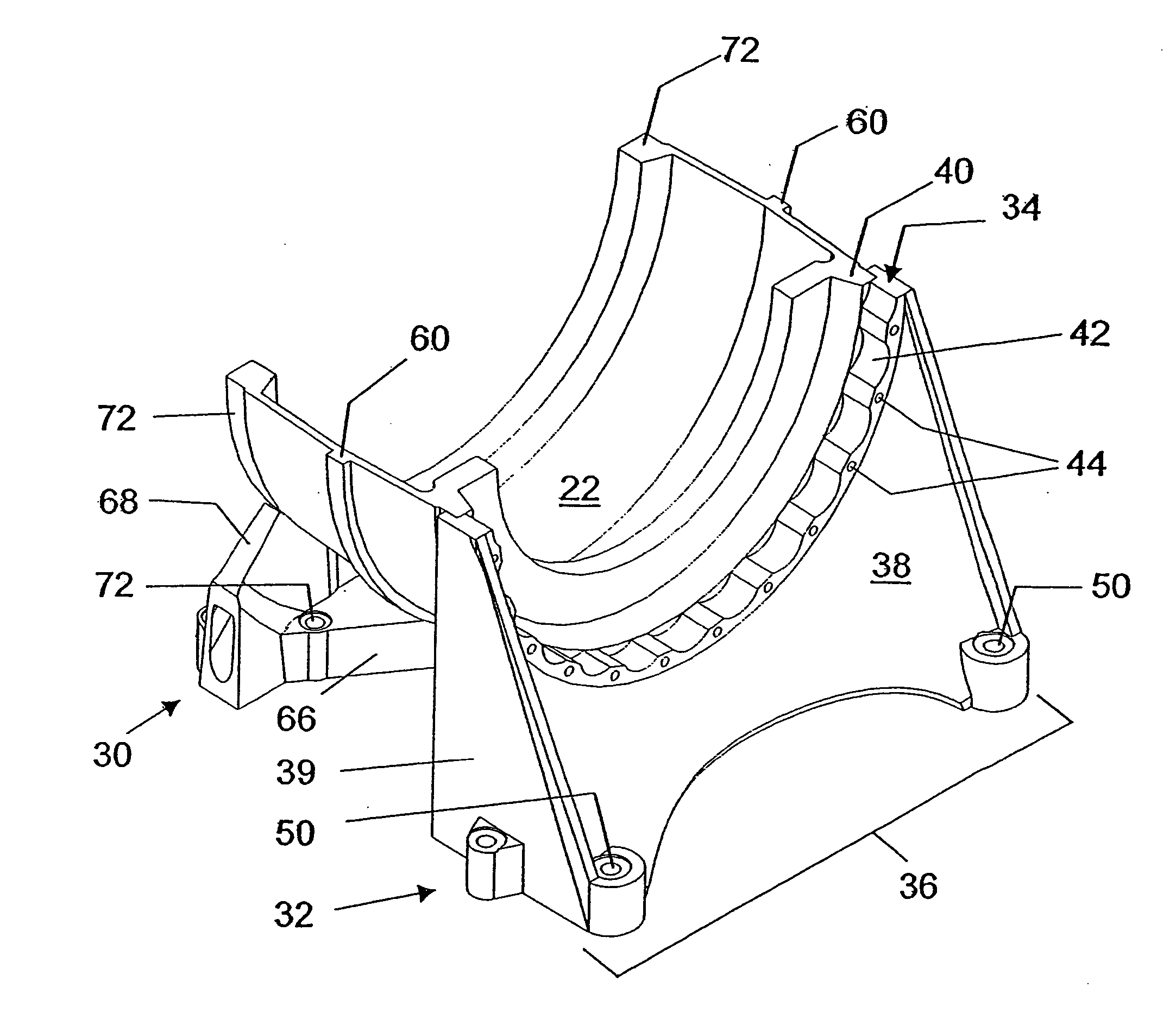
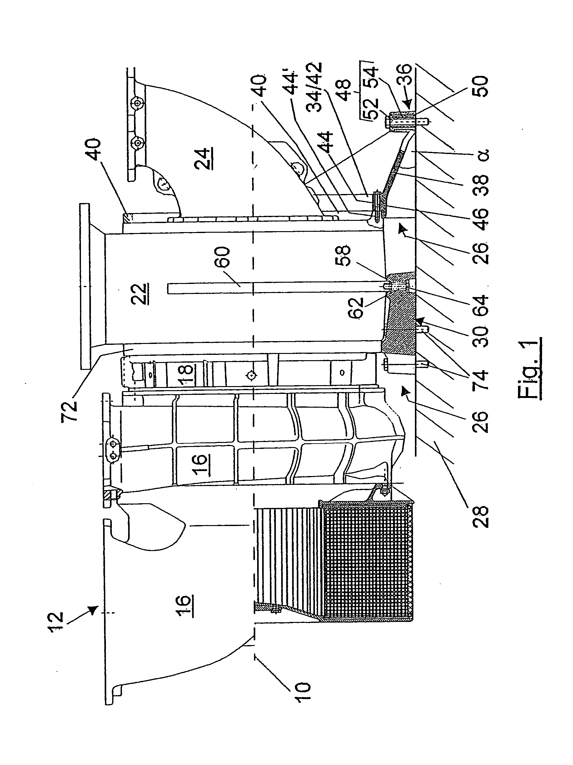
[0028]FIG. 1 shows a side view, along its longitudinal axis 10, of a turbocharger 12 with a turbocharger casing 14 which, along the longitudinal axis 10, comprises a compressor casing 16, a bearing casing 18 and a turbine casing 20. The turbine casing 20, for its part, includes a gas outlet casing 22 and a gas inlet casing 24. The turbocharger 12 is secured to a base 28 by means of a securing device 26 according to the invention. The securing device 26 has a first foot 30, which can be fixed in the base, and a second foot 32, which can be fixed in the base at an axial distance therefrom. The feet are in each case connected to the turbocharger casing 14, specifically in each case at the gas outlet casing 22, with the first foot 30 being arranged on the gas outlet casing 22 on the compressor side and the second foot 32 being arranged on the gas outlet casing 22 on the turbine side.

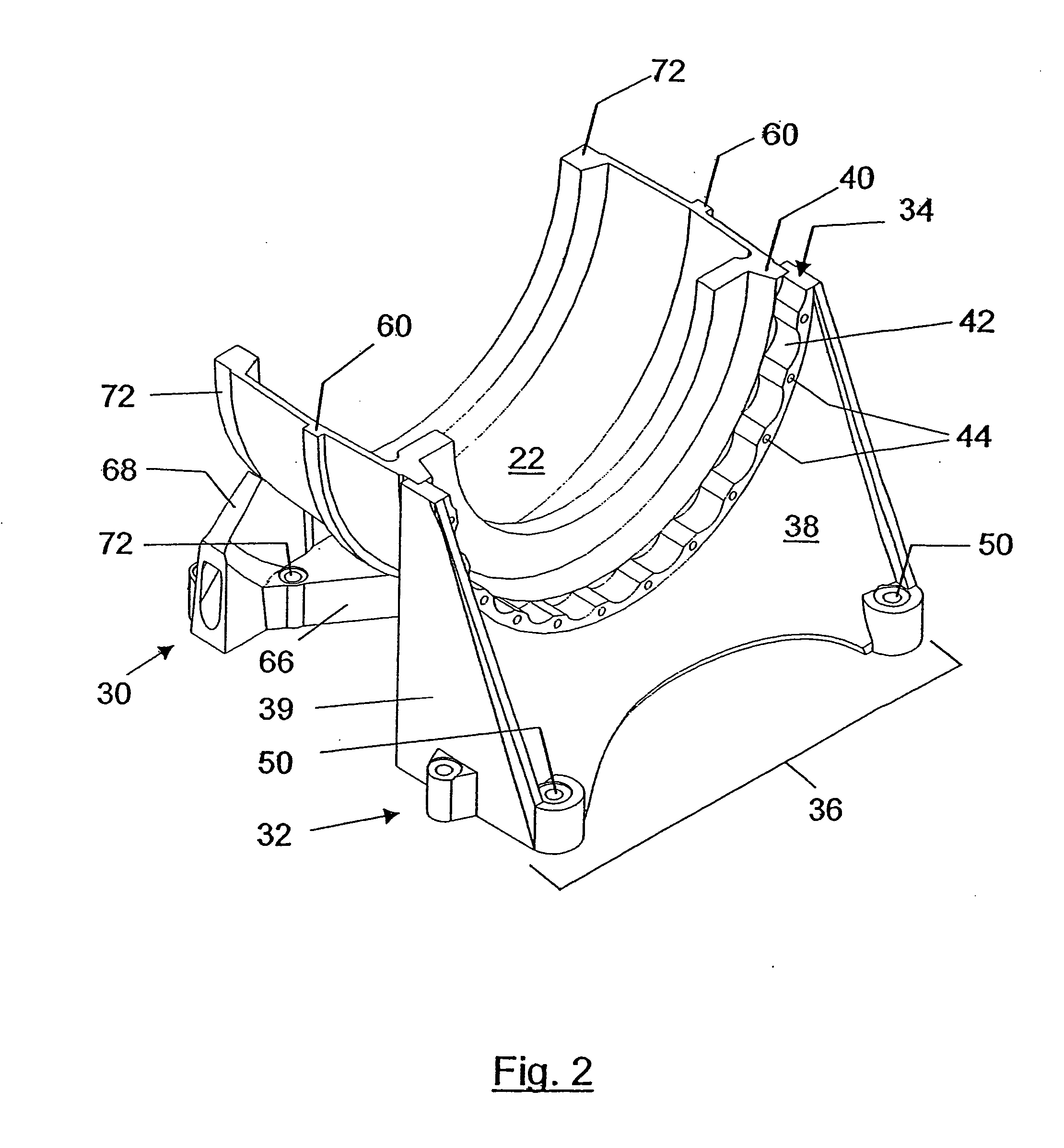
[0029] As can be seen from FIGS. 1, 2 and 3, the second foot 32, for connection to the turbocharger casi...


PUM


Abstract

The invention proposes a securing device (26) for securing a turbocharger (12) comprising a turbocharger casing (14) to a base (28). The securing device (26) has a first foot (30) which can be fixed in the base (28) and a second foot (32) which can be fixed in the base (28), it being possible for the two feet (30, 32) to be connected to the turbocharger casing (14) at an axial distance from one another. The second foot (32) has a casing connection region (34), which can be connected to the turbocharger casing (14), and a base connection region (36), which can be connected to the base (28). The casing connection region (34) is designed in the form of a partial circle arc or circle arc. An axial strut arrangement (38) connects the casing connection region (34) and the base connection region (36) and includes an angle α in the range from 0° to 60° with the base (28).

Description

DESCRIPTION [0001] 1. Technical Field [0002] The invention relates to a securing device for turbochargers in accordance with the features of the preamble of patent claim 1. [0003] 2. Prior Art [0004] Securing devices for turbochargers have to perform various roles. There are securing devices with just one foot and securing devices with two feet. An advantage of securing devices with two feet is that the dismantling and installation required for maintenance work is generally easier and quicker than in the case of securing devices with just one foot. [0005] In the case of securing devices with two feet, the feet are arranged on the turbocharger at an axial distance from one another and can be secured to the base. They are used to support and fix the turbocharger with respect to the base, to absorb vibrations in the turbocharger, so that they are not completely transmitted to the base, and to compensate for thermally induced dilation of the turbocharger casing. To absorb the vibrations...

Claims


Application Information

Patent Timeline
IPC IPC(8): F02B39/00F01D25/28F02C6/12
CPCF01D25/28F05D2220/40F02C6/12F02B67/10
Inventor BATTIG, JOSEF
Owner ABB TURBO SYST
Why Eureka
Try Eureka