
Image sensor and method therefor

a technology of image sensor and stepping motor, which is applied in the field of image sensor, can solve the problems of increasing the cost of production, affecting and the inability of the stepping motor to stably drive the scanning module, etc., and achieves the effect of increasing the brightness of the lamp and enhancing the scan resolution

Inactive Publication Date: 2005-01-27
AVISION
View PDF18 Cites 6 Cited by
  • Summary
  • Abstract
  • Description
  • Claims
  • Application Information

AI Technical Summary

Benefits of technology

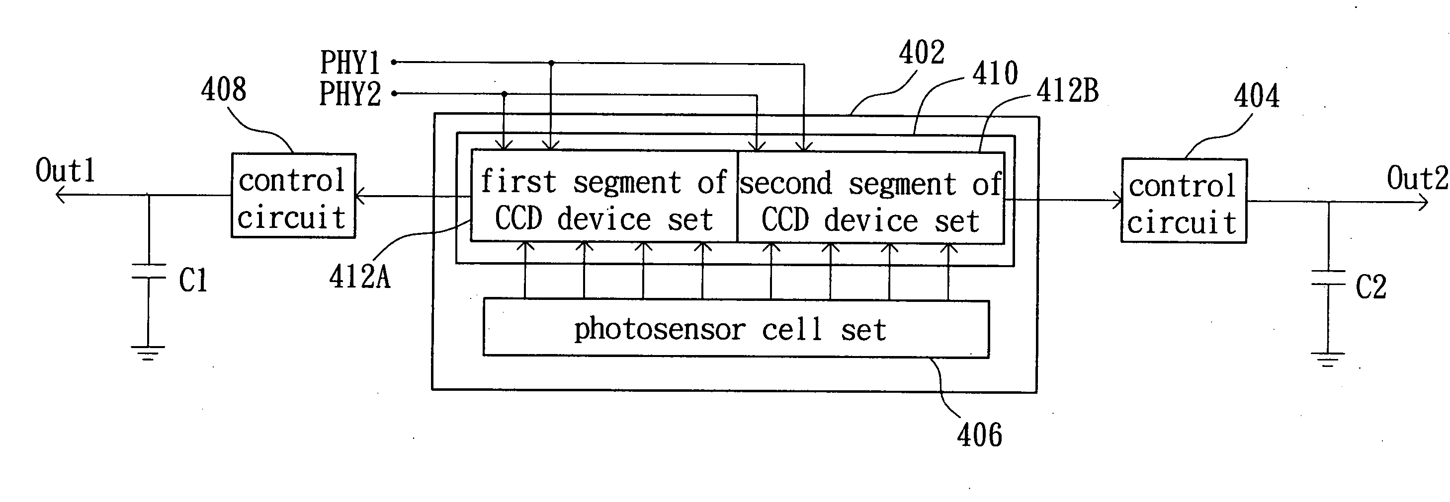
[0011] It is therefore an object of the invention to provide an image sensor and a method therefor, wherein at least one set of a red-light photosensor, a green-light photosensor and a blue-light photosensor is added in conjunction with a proper arrangement of the lens module. Thus, the number of scan lines read by a CCD module in the moving direction of the CCD module in the same exposure time may be at least doubled to enhance the scan resolution without improving the stepping motor or increasing the lamp brightness.
[0013] The image sensor reads 3K corresponding adjacent scan lines in each step of the motor, where the motor moves the image sensor by K scan lines relative to the to-be-scanned document along a specific axis, and continues reading until all the scan lines have been read. Thus, each scan line may be sequentially read by a red-light photosensor, a green-light photosensor, and a blue-light photosensor among the 3K photosensors. So, the scan resolution may be increased to K times of the original scan resolution without increasing the motor speed and the scanning speed.
[0014] The invention also achieves the above-identified object by providing an image reading method applied to the above-mentioned image sensor to read a number of scan line in the to-be-scanned document and thus to acquire the image. The image reading method includes the steps of: reading 3K scan lines respectively with the K red-light photosensors, the K green-light photosensors, and the K blue-light photosensors; moving the image sensor by K scan lines relative to the to-be-scanned document along a specific axis in a step of a motor of the image scanning device; reading 3K corresponding adjacent scan lines; and repeating the relative movement between the image sensor and the to-be-scanned document along the specific axis until all of the scan lines have been read. So, the scan resolution may be increased to K times of the original scan resolution without increasing the motor speed and the scanning speed.

Problems solved by technology

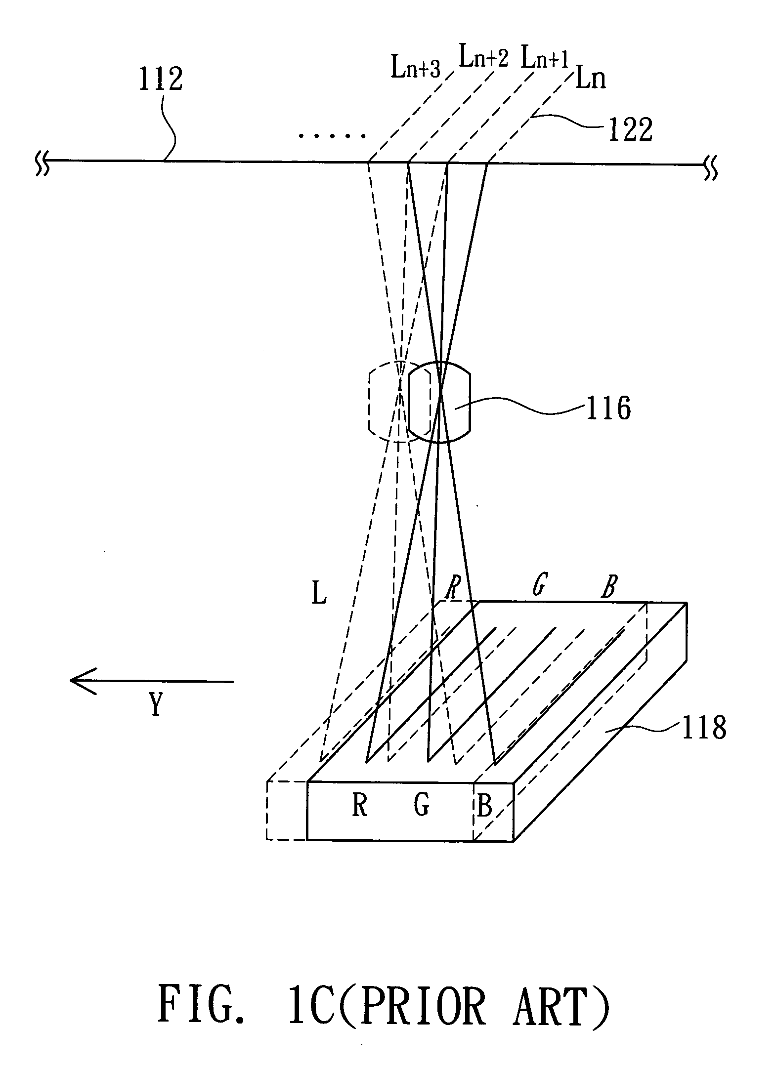
At this time, the stepping motor may not stably drive the scanning module, and a larger or a more expensive stepping motor has to be used.
Thus, the brightness of the lamp 110 has to be increased by, for example, increasing the number of lamps or applying a high voltage to the lamp, which economically increases the cost of production or shortens the lifetime of the lamp.

Method used


Image

  • Image sensor and method therefor
  • Image sensor and method therefor
  • Image sensor and method therefor

Examples


Embodiment Construction

[0024] The image sensor of the invention used in a CCD module of a scanner is described as an example to illustrate how to enhance the scan resolution. FIG. 2A is a schematic illustration showing an image sensor for a scanner according to a preferred embodiment of the invention. Referring to FIG. 2A, a scanner 200 includes an upper cover 210 and a base 220, which includes a scan platen 221, an optical module 223 and a circuit board 225. The scan platen 221 is provided for a to-be-scanned document 222 (e.g., a reflective type of document) to be placed thereon. The optical module 223 includes a light source 224, a reflecting mirror 226, a lens module 227 and a CCD module 228. When the document is scanned, light rays L are projected from the light source 224 of the optical module 223 onto the to-be-scanned document 222. Then, the light rays L reflected by the to-be-scanned document 222 enter the optical module 223. Then, the light rays L are reflected by the reflecting mirror 226, focu...


PUM


Abstract

An image sensor includes P (P≧2) red-light, P green-light and P blue-light photosensors and is mounted in an image scanning device to expose and read multiple scan lines of a to-be-scanned document. The scanning device includes a driving device for driving the image sensor to move relative to the document. When the image sensor acquires an image of the document, the P red-light photosensors, the P green-light photosensors and the P blue-light photosensors read 3P adjacent scan lines respectively in each exposure. The image sensor continues to read the 3P corresponding adjacent scan lines when the driving device further drives the image sensor to move by P scan lines relative to the document in a specific direction in each step of the driving device. The driving device continues to drive the image sensor to move relative to the document until all the scan lines have been read.

Description

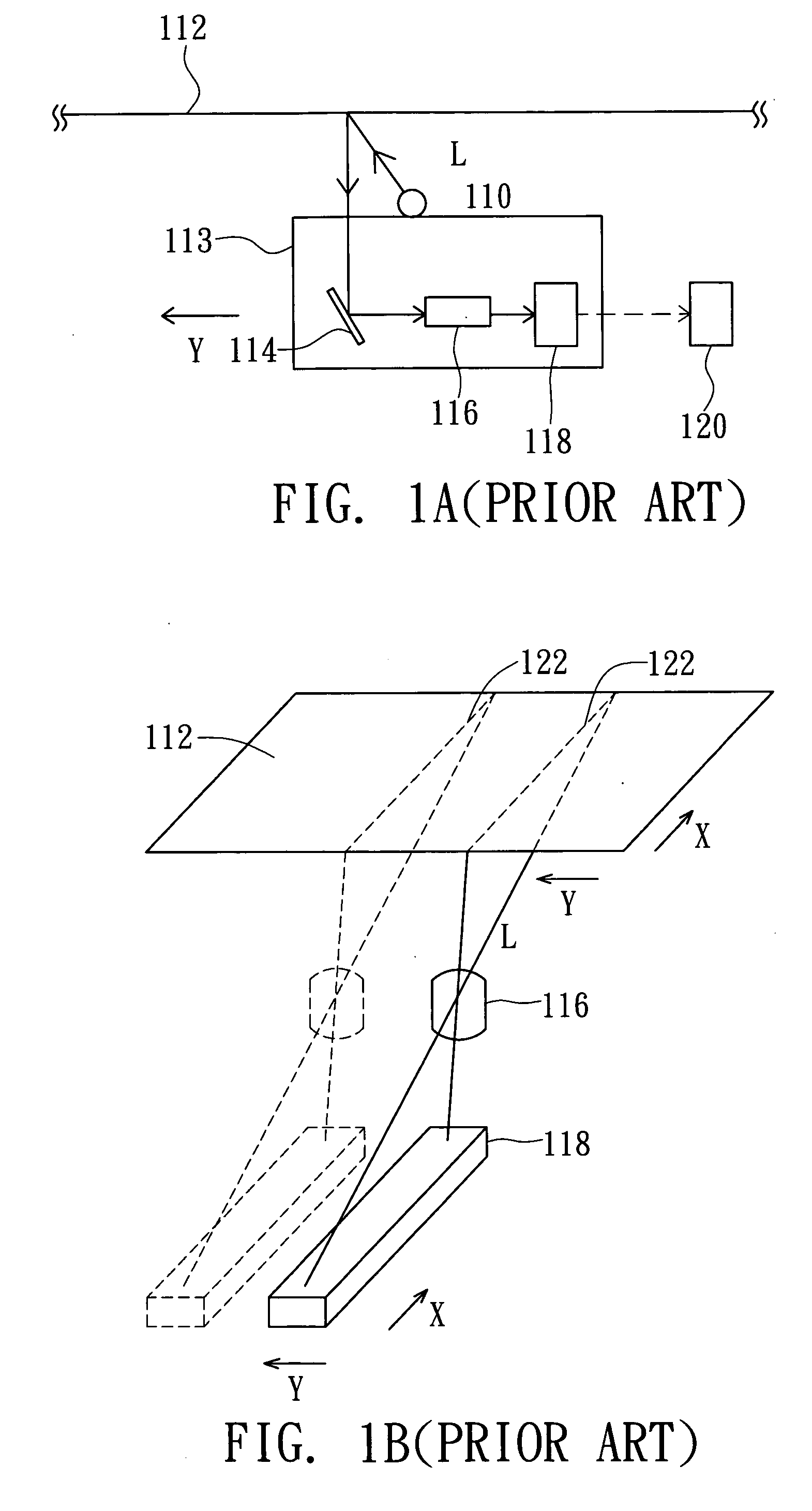
[0001] This application claims the benefit of Taiwan application Serial No. 092119894, filed Jul. 21, 2003, the subject matter of which is incorporated herein by reference. BACKGROUND OF THE INVENTION [0002] 1. Field of the Invention [0003] The invention relates to an image sensor and a method therefor, and more particularly to an image sensor including at least two sets of photosensors composed of a red-light photosensor, a green-light photosensor and a blue-light photosensor to enhance the resolution in the moving direction of the image sensor, and a method therefor. [0004] 2. Description of the Related Art [0005]FIG. 1A is a schematic illustration showing an optical path in a conventional scanner for scanning a document. Taking a reflective type of document as an example, a typical scanner acquires an image by projecting light rays L from a lamp 110 onto a to-be-scanned document 112. Then, the light rays L enter the optical module 113 and is reflected by a reflecting mirror 114, ...

Claims


Application Information

Patent Timeline
Patent Type & Authority Applications(United States)
IPC IPC(8): H04N1/192H04N1/195H04N1/48
CPCH04N1/192H04N1/486H04N1/195
Inventor CHUEH, CHUANG-HUA
Owner AVISION
Learn More