Drift-free video encoding and decoding method and corresponding devices

a video encoding and decoding technology, applied in the field of drift-free video encoding and decoding methods and corresponding devices, can solve the problems of lack of coding efficiency, shortcoming of layer-based scalability schemes, and inability to perfect the video sequence at lower resolution, so as to achieve better coding efficiency

Inactive Publication Date: 2005-01-27
KONINKLIJKE PHILIPS ELECTRONICS NV
View PDF3 Cites 56 Cited by
  • Summary
  • Abstract
  • Description
  • Claims
  • Application Information

AI Technical Summary

Benefits of technology

The proposed solution is remarkable in the sense that the global structure of the decomposition tree in the 3DS analysis is preserved aid no extra information is sent to correct the drift effect (only the decomposition / reconstruction mechanism is changed). If no motion estimation / compensation is performed at full resolution, it is a low-cost solution in terms of complexity. If motion compensation is introduced in the high spatial subbands, a better coding efficiency is provided.

Problems solved by technology

A short-coming of these layer-based scalability schemes comes however from their lack of coding efficiency.
However, when motion compensation is used in the 3D analysis scheme, this method does not allow a perfect reconstruction of the video sequence at lower resolution, even at very high bit-rates: this phenomena, referred to as drift in the following description, lowers the visual quality of the scalable solution compared to a direct encoding at the targeted final display size.
Yet, it is known that MC is unavoidable to achieve a good coding efficiency, and the likelihood of a unique global motion is small enough to eliminate this particular case in the following paragraphs.
However, in said document, the described scheme, in addition to being quite complex, implies the sending of an extra information (the drift correction necessary to correctly synthesize the upper resolution) in the bitstream, thus wasting some bits (the solution described in the document “Multiscale video compression .

Method used


Image

  • Drift-free video encoding and decoding method and corresponding devices
  • Drift-free video encoding and decoding method and corresponding devices
  • Drift-free video encoding and decoding method and corresponding devices

Examples


Embodiment Construction

The proposed solution (i.e. a spatial scalability with no drift in a motion compensated 3D subband codec) is now explained with reference to its two main steps: (a) motion compensation at the lowest resolution, (b) encoding the high spatial subbands.

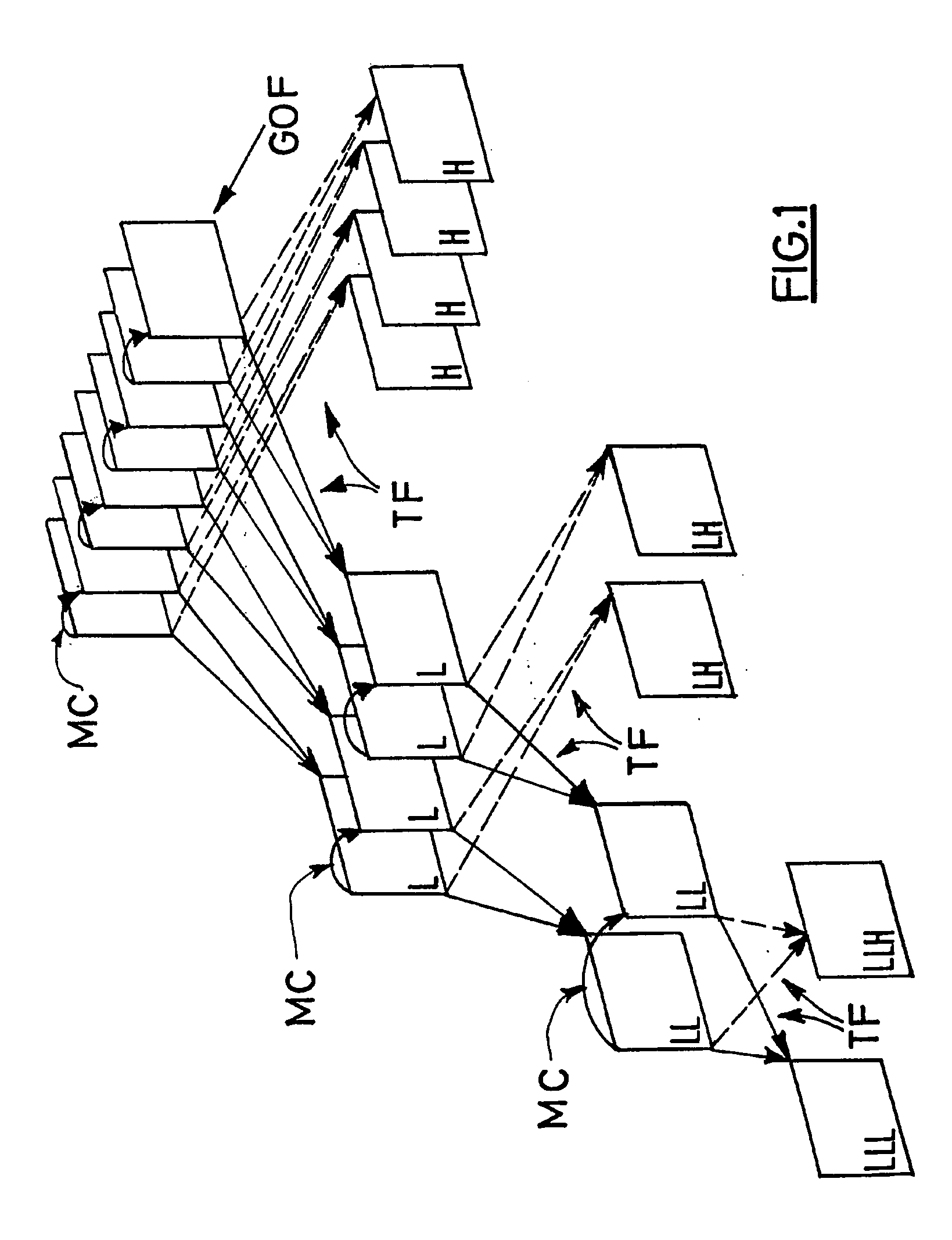
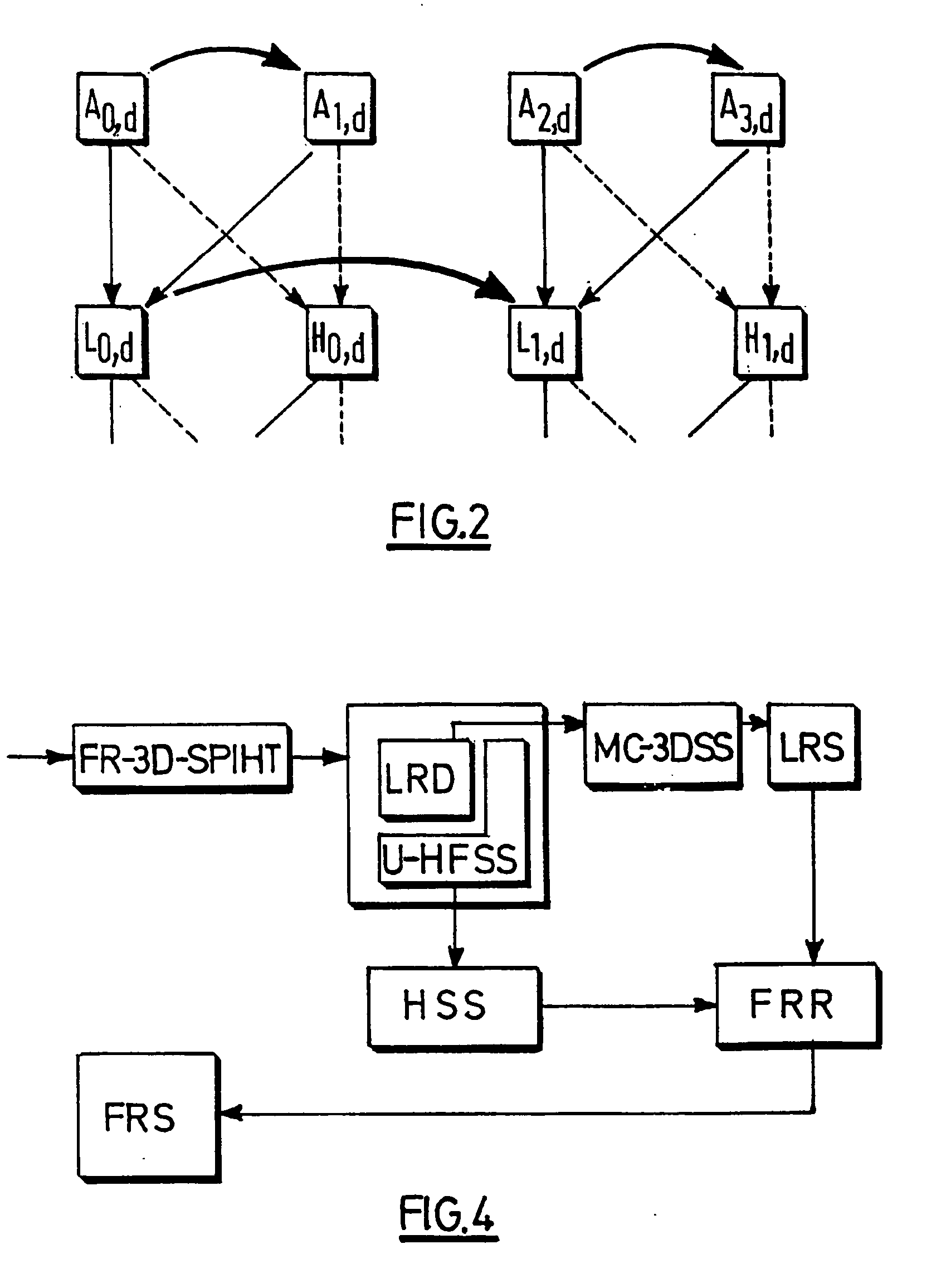
First in order to avoid drift at lower resolutions, Motion Compensation (MC) is applied at this level. Consequently, as illustrated in FIG. 2, one first downsizes (reference d) the GOF using wavelet filters, and the usual 3D subband MC-decomposition scheme is then applied to this downsized GOP instead of the fall-size GOF. In FIG. 2, the temporal subbands (L0,d, H0,d) and (L1,d, H1,d) are determined according to the well-known lifting scheme (H is first defined from A and B, and then L from A and H), and the dotted arrows correspond to the high-pass temporal filtering, the continuous ones to the low-pass temporal filtering, and the curved ones (between low frequency spatial subbands A of the frames of the sequence, referenced A0,d, A1...


PUM


Abstract

The invention relates to a video encoding method for the compression of a video sequence, comprising the steps of generating from the original video sequence, by means of a wavelet decomposition, a low resolution sequence, performing on said low resolution sequence a low resolution decomposition, by means of a motion compensated spatio-temporal analysis, generating from said low resolution decomposition a full resolution sequence, by means of an anchoring of the high frequency sparial subbands resulting from the wavelet decomposition to said low resolution decomposition and coding said full resolution sequence and the motion vectors generated during the motion compensated spatio-temporal analysis. The invention also relates to a corresponding decoding method, and to corresponding encoding and decoding devices.

Description

FIELD OF THE INVENTION The present invention relates to an encoding method for the compression of an original video sequence divided into successive groups of frames (GOFs) and to a corresponding decoding method. It also relates to corresponding encoding and decoding devices. BACKGROUND OF THE INVENTION The growth of the Internet and advances in multimedia technologies have enabled new applications and services. Many of them not only require coding efficiency but also enhanced functionality and flexibility in order to adapt to varying network conditions and terminal capabilities. Scalability answers these needs. Current video compression standards often use so-called hybrid solutions, based on a predictive scheme where each frame is temporally predicted from a reference frame (the prediction options being: zero value prediction, for the intra frames or I frames, forward prediction, for the P frames, or bi-directional prediction, for the B frames) and the obtained prediction error ...

Claims


Application Information

Patent Timeline
Patent Type & Authority Applications(United States)
IPC IPC(8): H04N7/30G06T9/00H03M7/30H03M7/36H04N7/26H04N7/32
CPCH04N19/13H04N19/63H04N19/615H04N19/1883H04N19/31H04N19/61H04N19/51
Inventor BOURGE, ARNAUDBARRAU, ERIC
Owner KONINKLIJKE PHILIPS ELECTRONICS NV
Why Eureka
Try Eureka