
Method and system for X-ray diffraction measurements using an aligned source and detector rotating around a sample surface

a detector and x-ray diffraction technology, applied in the field of x-ray analysis of materials, can solve the problems of large size, high cost, prone to reliability problems, and the use of conventional diffraction systems is limited to off-line “laboratory” settings, and the size, cost and performance limit the use of conventional diffraction systems

Active Publication Date: 2005-01-27
X-RAY OPTICAL SYSTEM INC +1
View PDF29 Cites 11 Cited by
  • Summary
  • Abstract
  • Description
  • Claims
  • Application Information

AI Technical Summary

Problems solved by technology

Conventional diffraction systems are large, expensive and prone to reliability problems.
Their size, cost, and performance limit their use to off-line “laboratory” settings.

Method used


Image

  • Method and system for X-ray diffraction measurements using an aligned source and detector rotating around a sample surface
  • Method and system for X-ray diffraction measurements using an aligned source and detector rotating around a sample surface
  • Method and system for X-ray diffraction measurements using an aligned source and detector rotating around a sample surface

Examples


Embodiment Construction

)

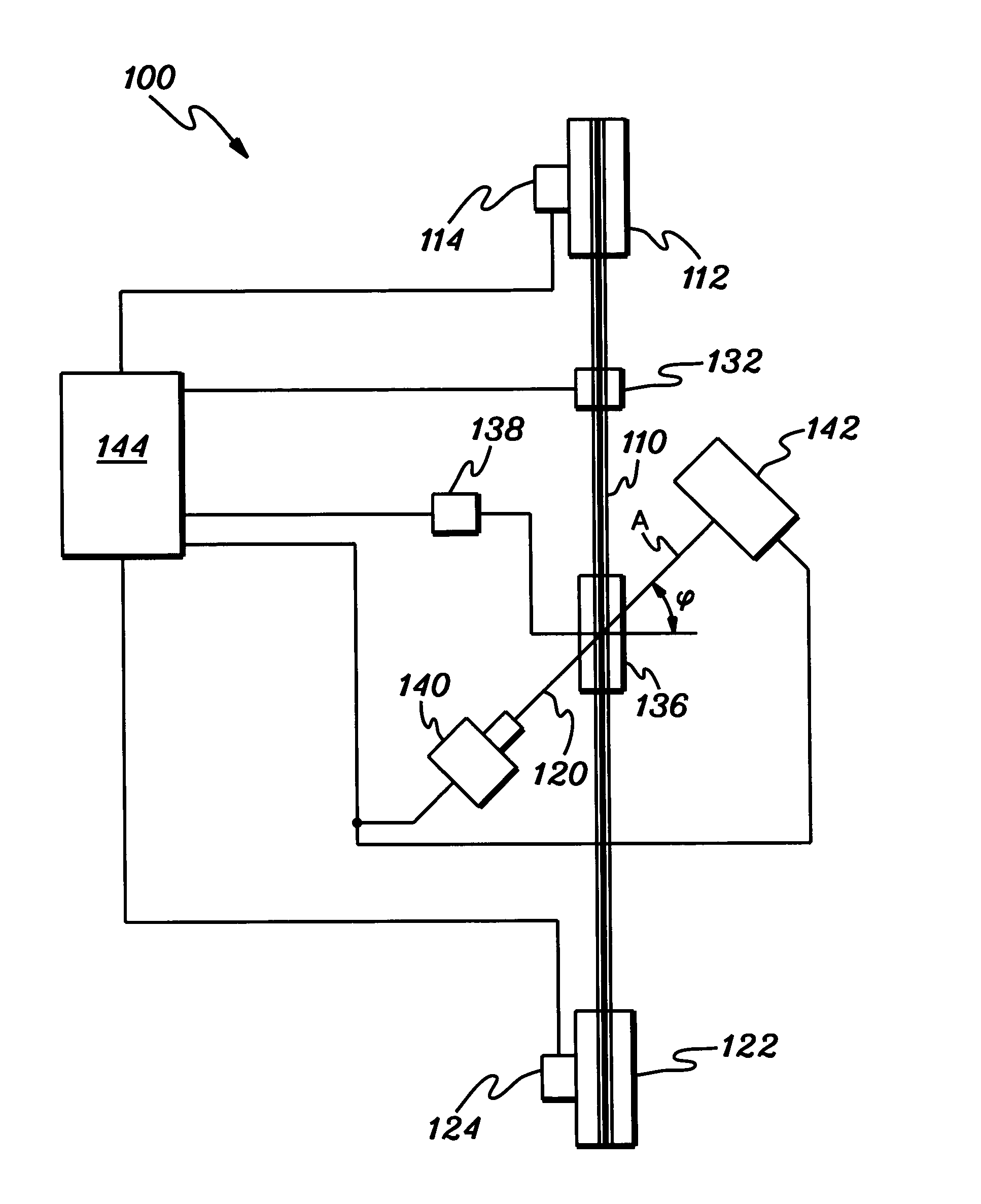
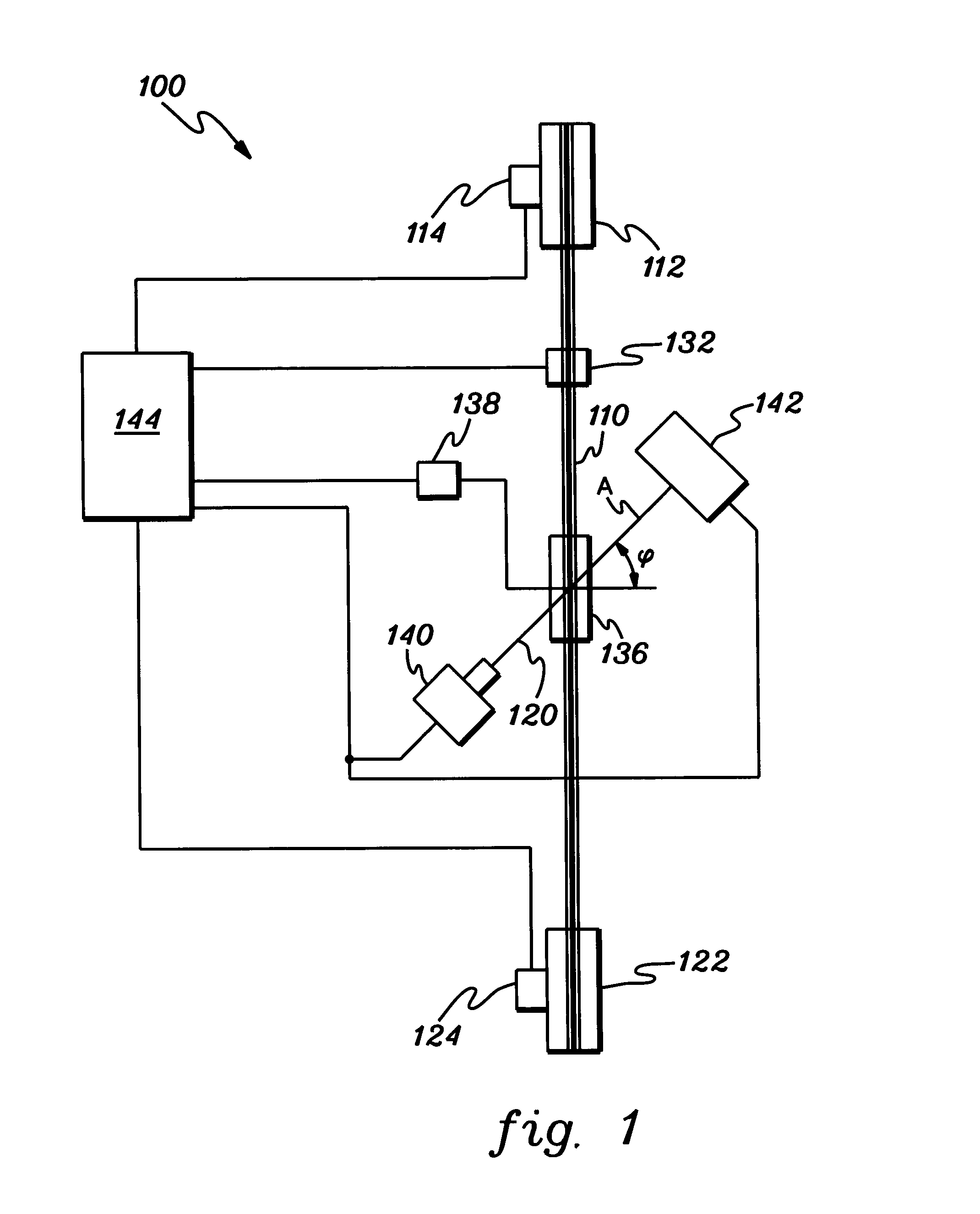
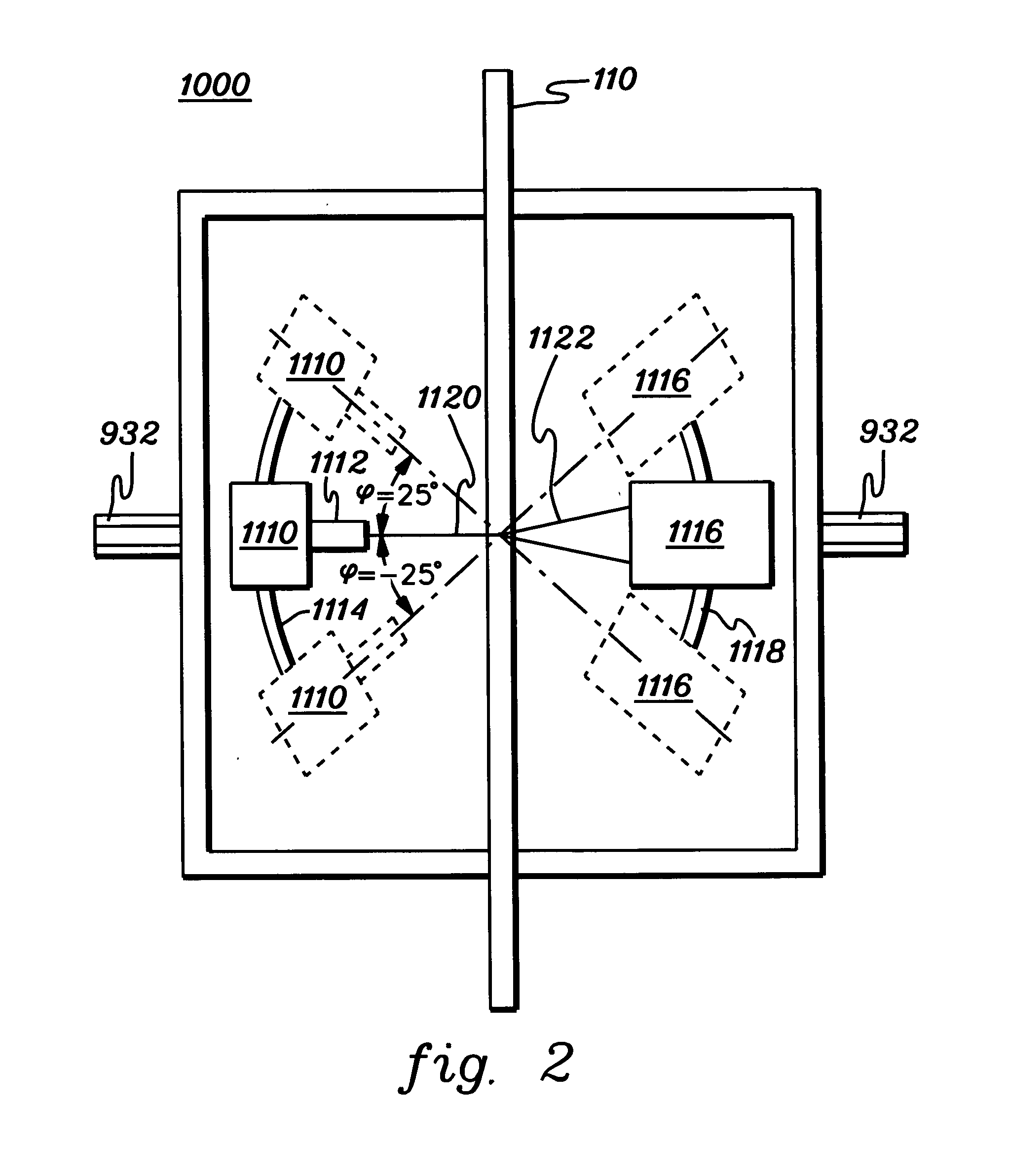
[0022]FIG. 1 shows an XRD system 100 for determining the crystallographic texture of a reel-to-reel spool-fed continuous sample 110.

[0023] In this example, the sample is a tape-like configuration, having a high aspect ratio over the sample area. For example, in a superconducting tape embodiment of the present invention as disclosed in copending Application entitled “METHODS FOR FORMING SUPERCONDUCTOR ARTICLES AND XRD METHODS FOR CHARACTERIZING SAME” filed o / a 16 Jul. 2003 in the name of Jodi Reeves as Docket# 1014-SP231, Ser. No. 60 / 487,739, the entirety of which is hereby incorporated herein by reference, the width of the tape is generally on the order of about 0.4-10 cm, and the length of the tape is typically at least about 100 m, most typically greater than about 500 m. Indeed, embodiments of the present invention provide for superconducting tapes that include a substrate having a length on the order of 1 km or above. Accordingly, the substrate may have an aspect ratio that is...


PUM

PropertyMeasurementUnit
angleaaaaaaaaaa
lengthaaaaaaaaaa
lengthaaaaaaaaaa

Abstract

An x-ray diffraction measurement apparatus for measuring a sample, having an x-ray source and detector coupled together in a combination for coordinated rotation around the sample, such that x-ray diffraction data can be taken at multiple phi angles. The apparatus may provide a pole figure representation of crystal orientation of the sample, wherein the pole figure represents the crystal alignment, and a full width half maximum value is calculated from the pole figure for crystal alignment quantification. Data may be taken at discrete positions along a length of the sample, and the sample is in a fixed position during measuring; or data may be taken continuously along a length of the article, as the sample continuously moves along its length in a movement path between the source and detector. The sample may be in the form of a tape, linearly passing through a measurement zone.

Description

CROSS-REFERENCE TO RELATED APPLICATIONS [0001] This application claims the benefit of U.S. Provisional Application No. 60 / 489,047, filed Jul. 22, 2003. This Provisional Application is hereby incorporated herein by reference in its entirety.FIELD OF THE INVENTION [0002] The present invention relates to x-ray analysis of materials. In particular, the present invention relates to x-ray diffraction techniques for analysis of sample surfaces, especially for in-situ measurement of samples during fabrication thereof. BACKGROUND OF THE INVENTION [0003] X-ray analysis techniques have been some of the most significant developments in twentieth-century science and technology. The use of x-ray diffraction, spectroscopy, imaging, and other x-ray analysis techniques has led to a profound increase in knowledge in virtually all scientific fields. [0004] One existing class of surface analysis is based on diffraction of x-rays directed toward a sample. The diffracted radiation can be measured and var...

Claims


Application Information

Patent Timeline
Patent Type & Authority Applications(United States)
IPC IPC(8): G01N23/207
CPCG01N23/207
Inventor GIBSON, DAVID M.GIBSON, WALTER M.HUANG, HUAPENGREEVES, JODI LYNN
Owner X-RAY OPTICAL SYSTEM INC
Learn More