
Packaging and applicator device including a coupling member enabling two receptacles to be united

a technology of coupling member and receptacle, which is applied in the direction of packaging goods, applications, brushes, etc., can solve the problems of affecting the overall size of the assembly constituted by the two receptacles united by the coupling member, and affecting the applicability of the devi

Inactive Publication Date: 2005-01-27
LOREAL SA
View PDF25 Cites 37 Cited by
  • Summary
  • Abstract
  • Description
  • Claims
  • Application Information

AI Technical Summary

Benefits of technology

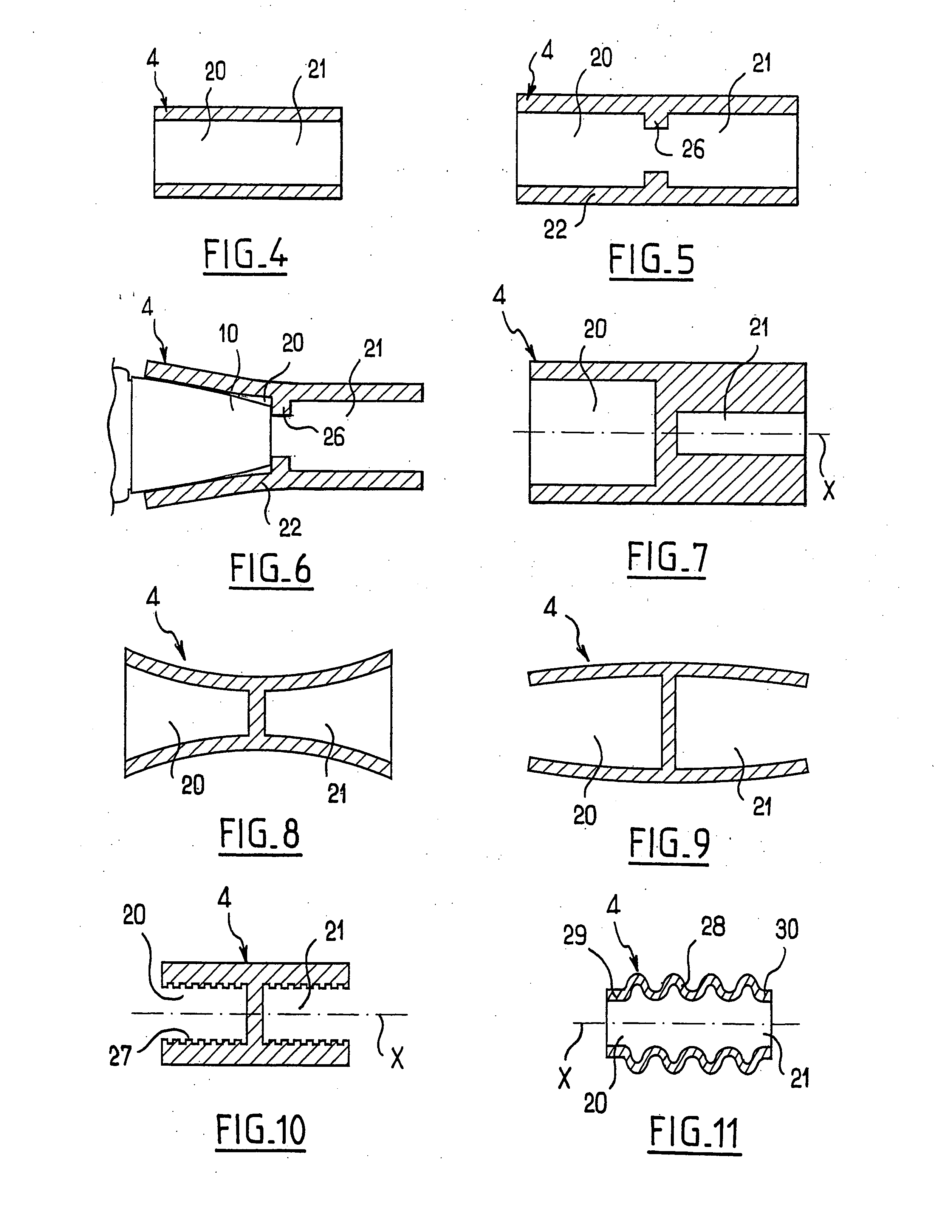
[0012] The coupling member may have at least one housing configured to be capable of receiving and holding by friction the cap of one of the receptacles. It is then possible when the closure cap carries an applicator member, to make use of the coupling member as a handle member, which can make handling the applicator member easier than when using the closure cap on its own, particularly when the axial size of the closure cap is quite small.
[0015] The coupling member may present elasticity, enabling it to adapt to the shape of the bodies or the caps of the receptacles it receives.
[0022] Such an arrangement can make it possible, for example, to ensure that air is not held captive in the corresponding housing when a receptacle is engaged therein.
[0031] The coupling member may be transparent or translucent. The coupling member may be configured to produce varying optical effects that are visible from the outside, for example goniochromatic effects, i.e. effects of color varying with viewing angle.

Problems solved by technology

Nevertheless, the total size of the assembly constituted by the two receptacles united by the coupling member would then tend to become cumbersome, particularly for being carried in a handbag, for example.
Furthermore, the need to make setbacks in the bodies of the receptacles for co-operating with the studs of the coupling member can be undesirable, in particular in terms of appearance.

Method used


Image

  • Packaging and applicator device including a coupling member enabling two receptacles to be united
  • Packaging and applicator device including a coupling member enabling two receptacles to be united
  • Packaging and applicator device including a coupling member enabling two receptacles to be united

Examples


Embodiment Construction

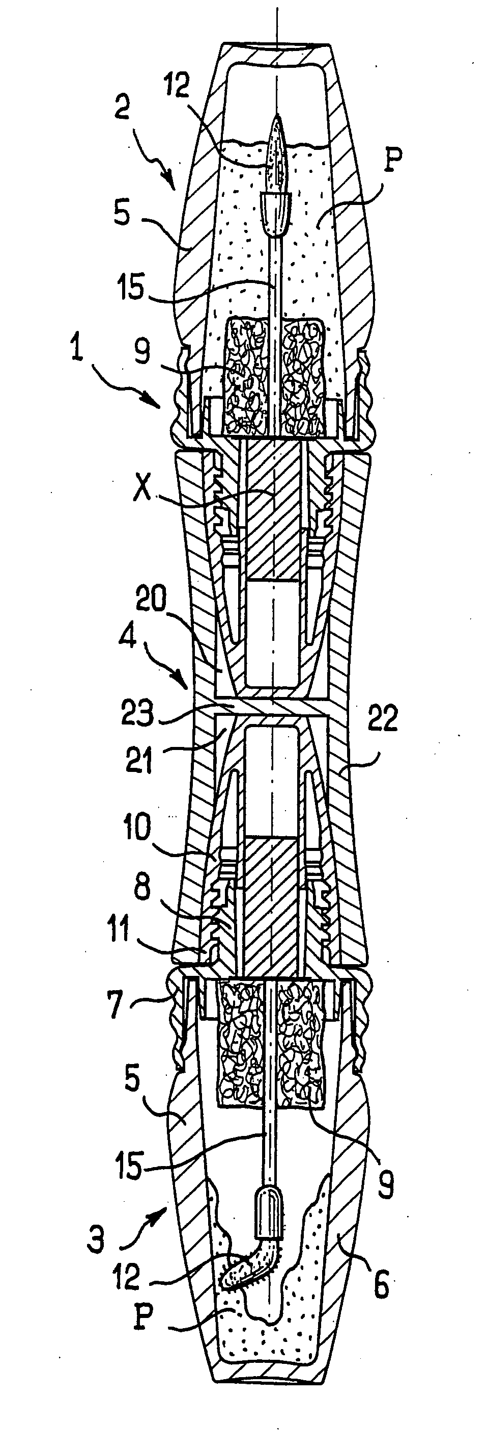
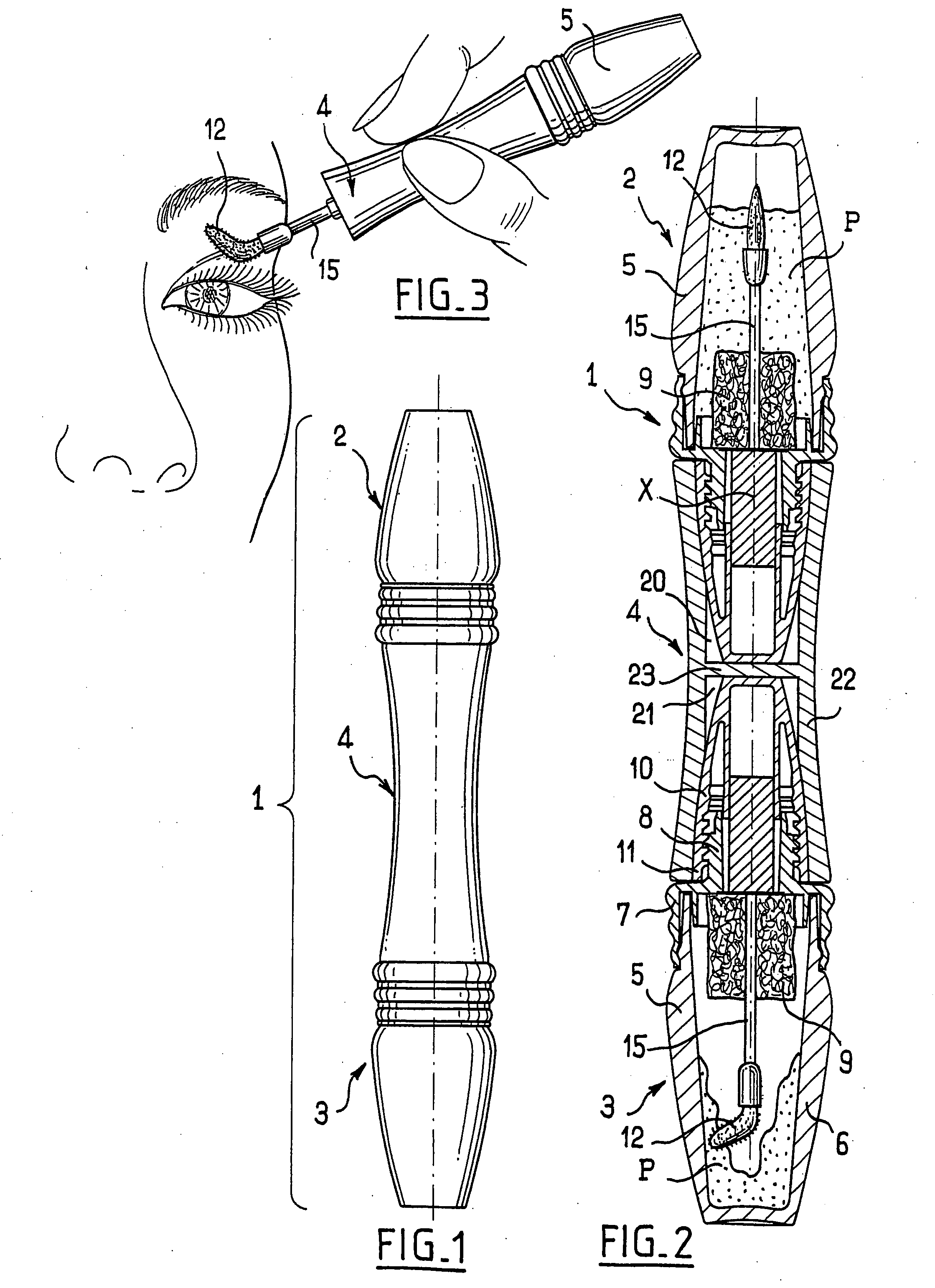
[0059]FIGS. 1 and 2 show a device 1 comprising two receptacles 2 and 3 united by a coupling piece 4.

[0060] As can be seen in particular in FIG. 2, each receptacle 2 or 3 comprises a body 5 containing a substance P. In the example shown, each body 5 comprises a bottom portion 6 surmounted by a fitting 7 defining a neck 8 for the receptacle and, where appropriate, capable of acting as a support for a wiper 9, e.g. constituted by a block of foam.

[0061] Each receptacle 2 or 3 also has a closure cap 10 including an assembly skirt 11 configured to screw onto the neck 8.

[0062] Each closure cap 10 serves as a handle member for an applicator member 12 which dips into the substance P inside the bottom portion 6 when the receptacle is closed, the applicator member being connected by means of a stem 15 to the closure cap 10. Each closure cap 10 presents an outside surface that is generally in then form of a dome with a flattened top.

[0063] In the example shown in FIGS. 1 and 2, the receptac...


PUM


Abstract

The present invention provides a packaging and applicator device comprising: at least two receptacles each containing one of a cosmetic and a care substance and each comprising a body and a removable closure cap; and at least one coupling member capable of uniting the two receptacles in line with each other, the coupling member being at least partially elastically deformable and comprising at least one housing configured to receive at least part of one the at least two receptacles and enabling it to be fixed to the coupling member.

Description

CROSS REFERENCE TO RELATED APPLICATIONS [0001] The present application claims the benefit of French patent application number 02-08247, filed Jul. 2, 2002 and U.S. provisional patent application No. 60 / 394,657, filed Jul. 10, 2002, the disclosures of which are hereby incorporated by reference. BACKGROUND OF THE INVENTION [0002] (i) Field of the Invention [0003] The present invention relates to packaging and applicator devices, in particular for applying at least one cosmetic or care product. [0004] The term “cosmetic” is used to mean a cosmetic product as defined in EEC Council Directive 93 / 35 of Jun. 13, 1993. [0005] (ii) Description of Related Art [0006] U.S. Pat. No. 6,035,865 discloses receptacles configured to be united by means of a coupling member having studs suitable for engaging in setbacks provided in the bottoms of the receptacles. Each receptacle is closed by a closure cap which may carry an applicator such as a brush, for example. In order to make the closure cap more ...

Claims


Application Information

Patent Timeline
IPC IPC(8): A45D34/06A45D40/24A45D40/26
CPCA45D34/06A45D40/262A45D40/24
Inventor GUERET, JEAN-LOUIS
Owner LOREAL SA
Learn More