

Variable capacity scroll compressor
- Summary
- Abstract
- Description
- Claims
- Application Information
AI Technical Summary
Benefits of technology
Problems solved by technology
Method used
Image

Examples
second embodiment
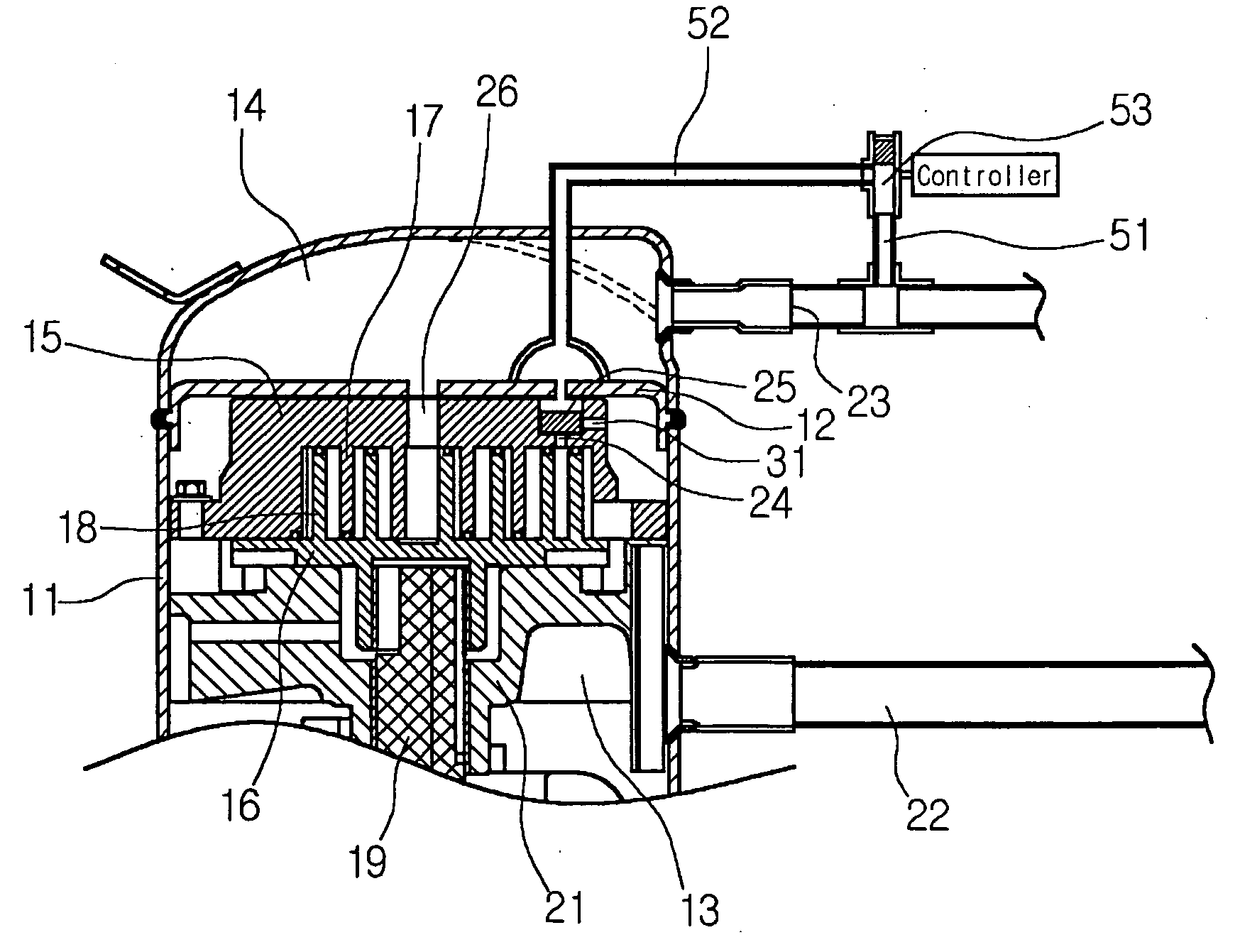
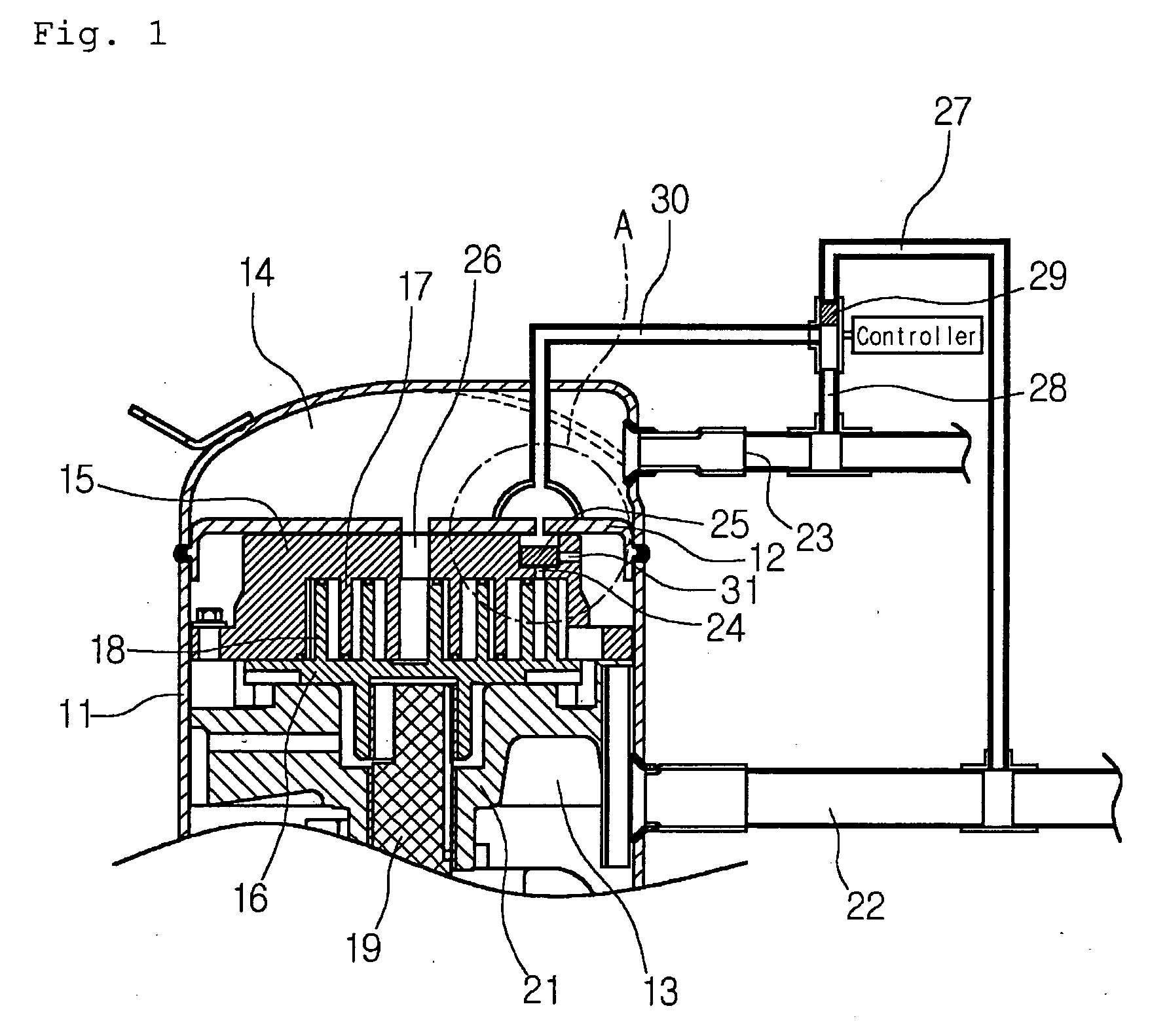
[0087]FIG. 7 shows a scroll compressor according to the present invention.
first embodiment
[0088] As shown in the drawing, the scroll compressor of this embodiment is identical to that of the first embodiment except for a connection structure around the control valve.
[0089] That is, a control passage 52, a control valve 53, and a high-pressure passage 51 are same as those in the first embodiment. However, the low-pressure passage 27 that is selectively connected to the control passage by the control valve in the first embodiment is not formed in this embodiment.
[0090] When the low-pressure passage 27 is not formed, the low-pressure of the intake passage 22 is not applied to the control passage 52 even when the control valve 53 moves downward in the drawing.
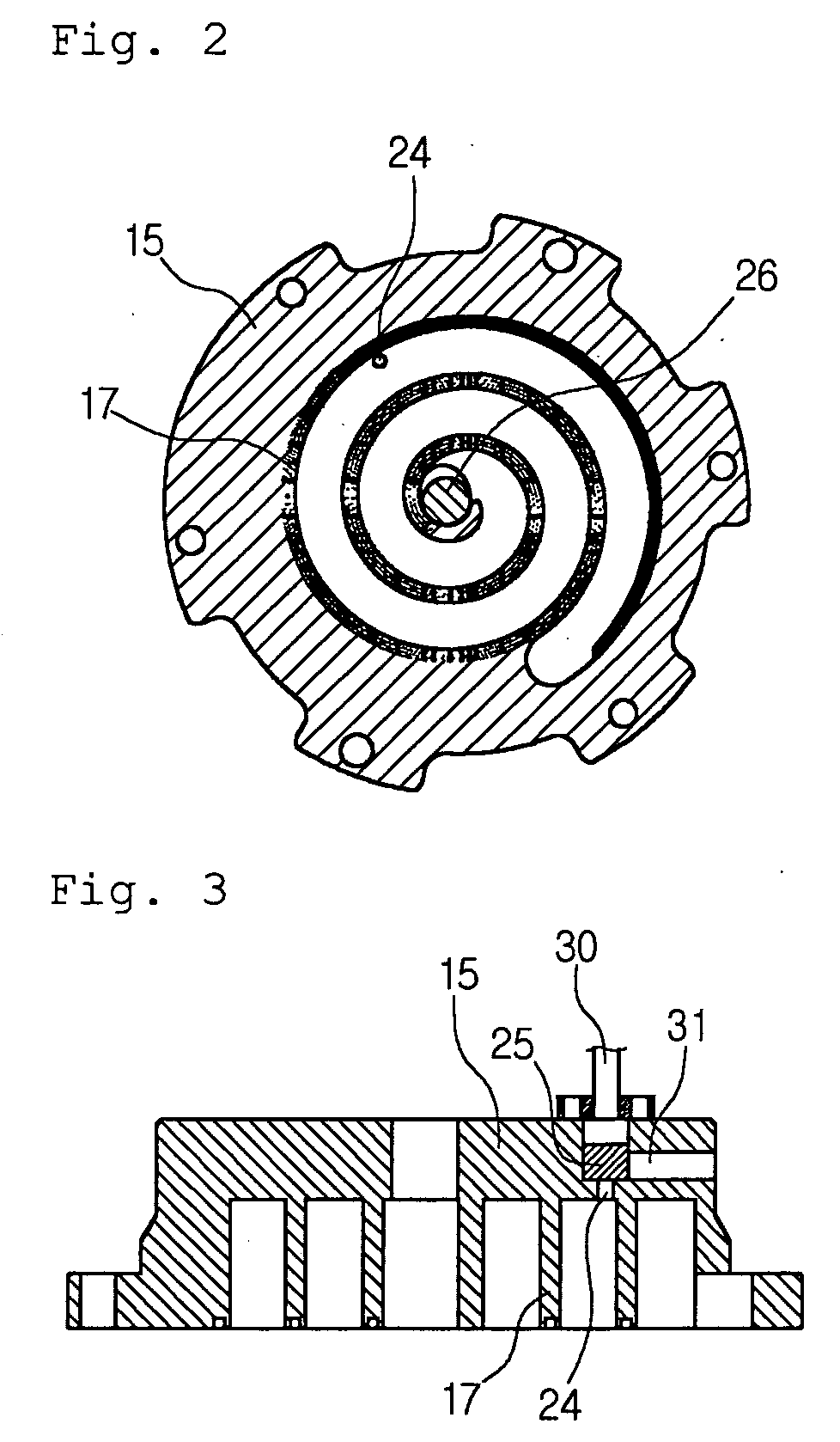
[0091] In such a case, since internal pressure of the control passage 52 is the pressure of a point where the bypass port 24 is formed and is lower than medium-pressure of fluid being compressed, the check valve 25 can be opened.
[0092] For this purpose, the check valve 25 can employ a floating valve that is freely mo...
PUM
 Abstract
Description
Claims
Application Information