Pump
- Summary
- Abstract
- Description
- Claims
- Application Information
AI Technical Summary
Benefits of technology
Problems solved by technology
Method used
Image

Examples
first exemplary embodiment
[0082] First Exemplary Embodiment
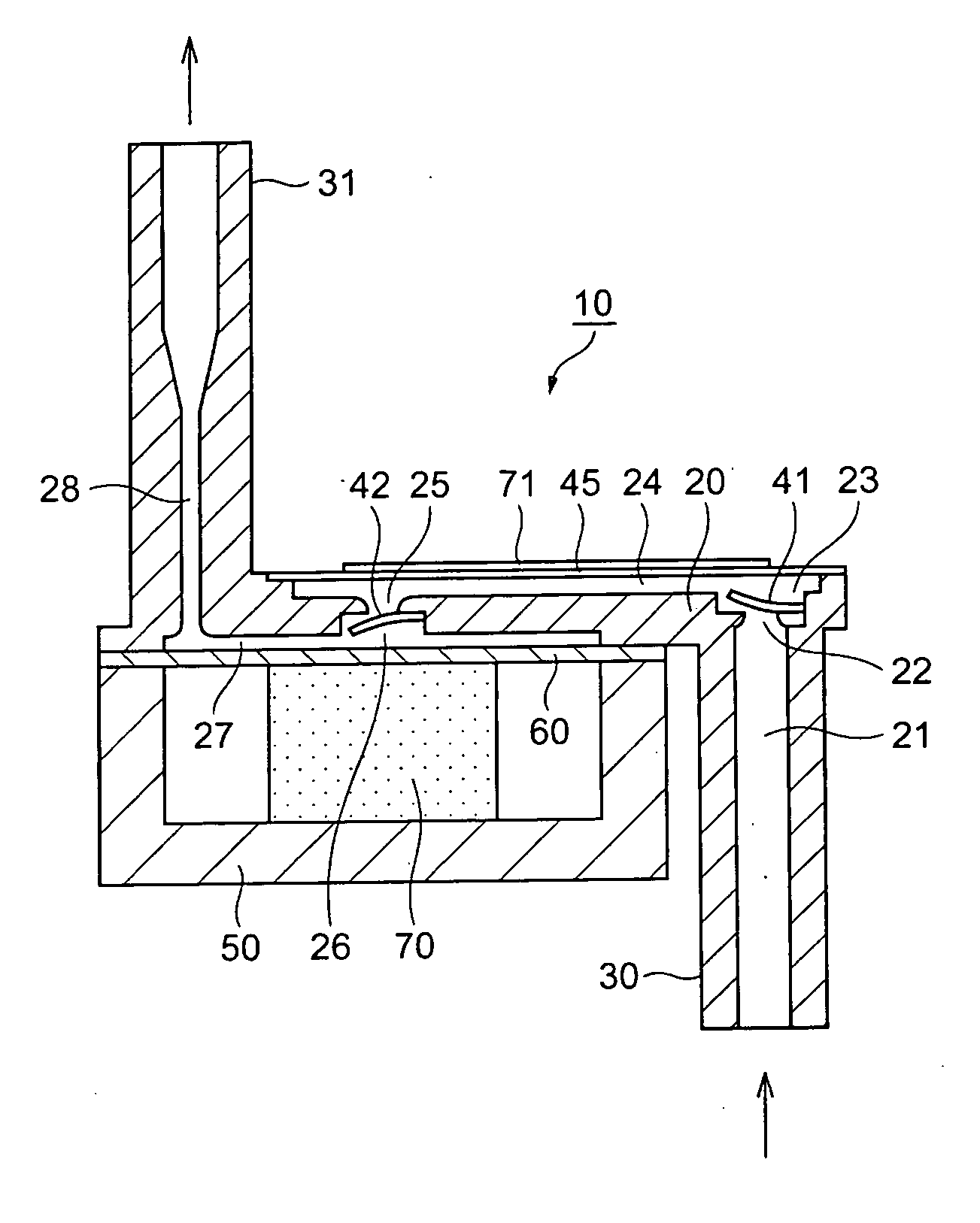
[0083] FIGS. 1 to 3 show a pump 10 according to a first exemplary embodiment.
[0084]FIG. 1 is a vertical cross-sectional schematic illustrating a structure of the pump 10 according to the first exemplary embodiment of the present invention. In FIG. 1, the pump 10 includes a cup-shaped case 50 to which a laminated piezoelectric element 70 is fixed, an inflow passage 21 to introduce a working fluid, an outflow passage 28 to discharge the working fluid, and a pump case 20 having a secondary pump chamber 24 and a primary pump chamber 27.
[0085] One end of the laminated piezoelectric element 70 is fixed to an inside bottom portion of the case 50 through a fixing device, such as adhesive. A primary pump chamber diaphragm 60 is closely fixed to both of a top surface of an edge portion of the case 50 and a top surface of the other end of the laminated piezoelectric element 70. The pump case 20 is fixed to the circumferential edge portion of the top surface o...
second exemplary embodiment
[0115] Second Exemplary Embodiment
[0116] Next, a second exemplary embodiment of the present invention will be described with reference to FIG. 4.
[0117] The pump according to the second exemplary embodiment has a basic structure similar to the aforementioned first exemplary embodiment, but is different from the first exemplary embodiment in that a part of a driving electrode 52 attached to the plate-shaped piezoelectric element 71 of the secondary pump chamber 24 is separated and forms a detecting electrode 53.
[0118]FIG. 4 is a schematic of the pump according to the second exemplary embodiment as seen from the secondary pump chamber diaphragm side. In FIG. 4, a part of the electrode 52 formed on the plate-shaped piezoelectric element 71 attached to the top surface of the secondary pump chamber diaphragm 45 is separated to form the detecting electrode 53.
[0119] Next, a function of the detecting electrode will be described. During the priming action, such as the time of starting the...
third exemplary embodiment
[0123] Third Exemplary Embodiment
[0124] Next, a third exemplary embodiment of the present invention will be described with reference to FIGS. 5 and 6. The pump according to the third exemplary embodiment has a basic structure similar to the aforementioned first exemplary embodiment, but is different from the first exemplary embodiment in that the pump includes a pressure sensor 90 in the primary pump chamber 27. Descriptions of constituent elements common to the first exemplary embodiment will be omitted.
[0125]FIG. 5 is a vertical cross-sectional schematic of the pump according to the third exemplary embodiment of the present invention, and FIG. 6 is a schematic of the driving circuit of the pump according to the third exemplary embodiment. In FIG. 5, two-stepped concave portion 35 is formed in an inside top wall of the primary pump chamber 27. The pressure sensor 90 made of the same material as the aforementioned plate-shaped piezoelectric element 71 is fixed to the step of the co...
PUM
 Abstract
Description
Claims
Application Information
 - Generate Ideas
- Intellectual Property
- Life Sciences
- Materials
- Tech Scout
- Unparalleled Data Quality
- Higher Quality Content
- 60% Fewer Hallucinations
Browse by: Latest US Patents, China's latest patents, Technical Efficacy Thesaurus, Application Domain, Technology Topic, Popular Technical Reports.
© 2025 PatSnap. All rights reserved.Legal|Privacy policy|Modern Slavery Act Transparency Statement|Sitemap|About US| Contact US: help@patsnap.com