
Environmentally protected and tamper resistant CATV drop connector and method

a drop cable and connector technology, applied in the direction of television connectors, couplings/cases, coupling device connections, etc., can solve the problems of physical tampering and vandalism of the drop cable, and the harsh environmental conditions of the drop cable in outdoor installations, so as to prevent moisture ingress, reduce friction, and high strength

Inactive Publication Date: 2005-01-27
PPC BROADBAND INC
View PDF15 Cites 11 Cited by
  • Summary
  • Abstract
  • Description
  • Claims
  • Application Information

AI Technical Summary

Benefits of technology

[0010] In accordance with the foregoing objects, the invention contemplates a connector in which the threaded member incorporates a high strength plastic thread which is slippery, i.e., low friction, and flexible and interferes with the threads of the port to which the connector is engaged. This eliminates the need for additional rubber sealing boots, messy silicone grease or RTV, or hard to turn dry pipe dopes. The plastic “nut” is molded as an integral part of the portion of the connector which seals the cable interface, thereby eliminating the usual joint between the nut and the connector body. This joint is typically sealed with an O-ring to prevent ingress of moisture; by eliminating the joint, there is no need for the O-ring or other sealing means and no possibility of moisture entry. By combining the conventional turned metal nut, the O-ring and molded plastic body in a single, injection molded part, the connector of the present invention is significantly reduced in cost.

Problems solved by technology

Connectors used on drop cables in outdoor installations are commonly exposed to harsher environmental conditions and, in addition, are subject to physical tampering and vandalism as, for example, in actual or attempted theft of services.

Method used


Image

  • Environmentally protected and tamper resistant CATV drop connector and method
  • Environmentally protected and tamper resistant CATV drop connector and method
  • Environmentally protected and tamper resistant CATV drop connector and method

Examples


Embodiment Construction

)

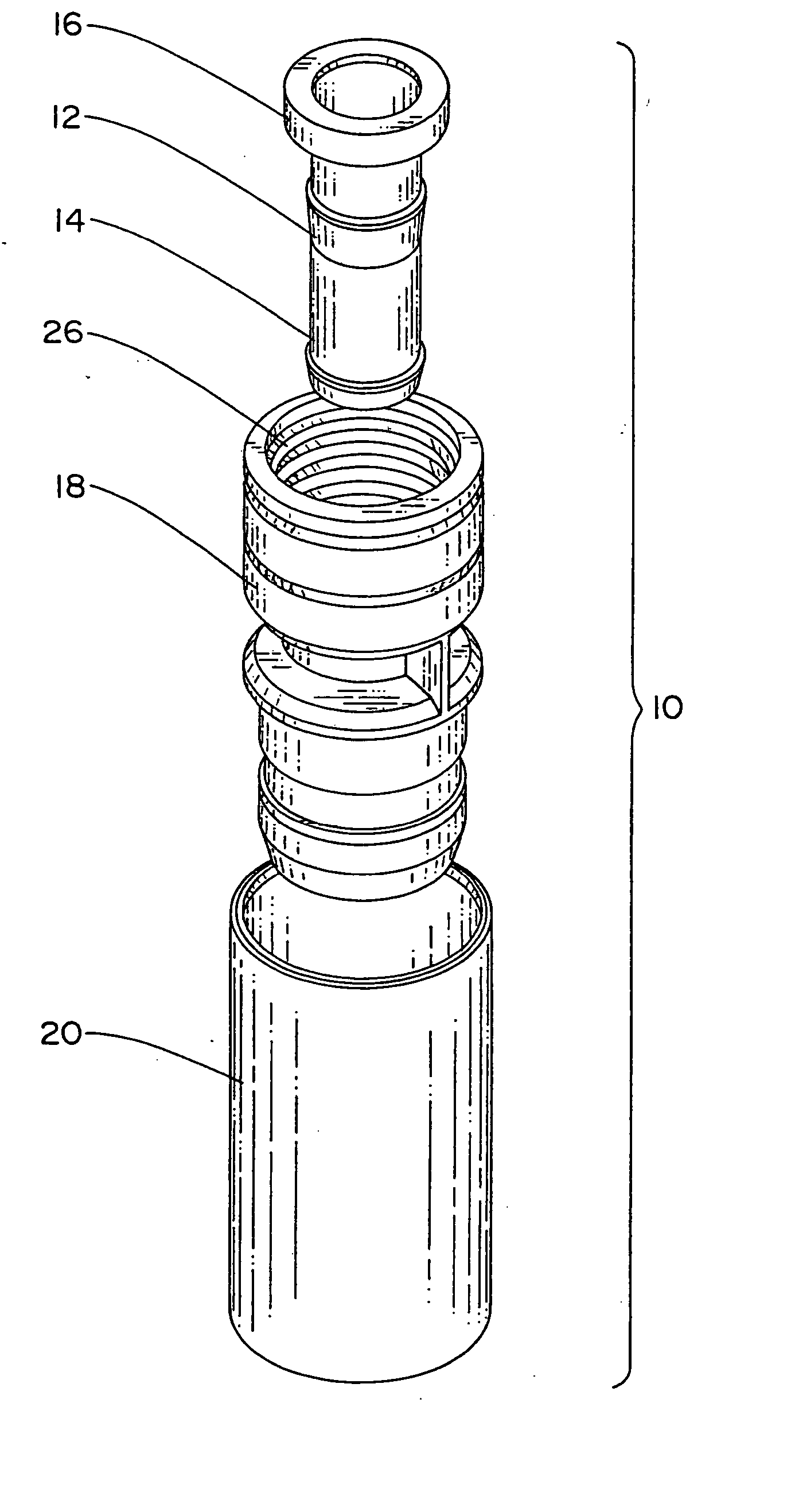
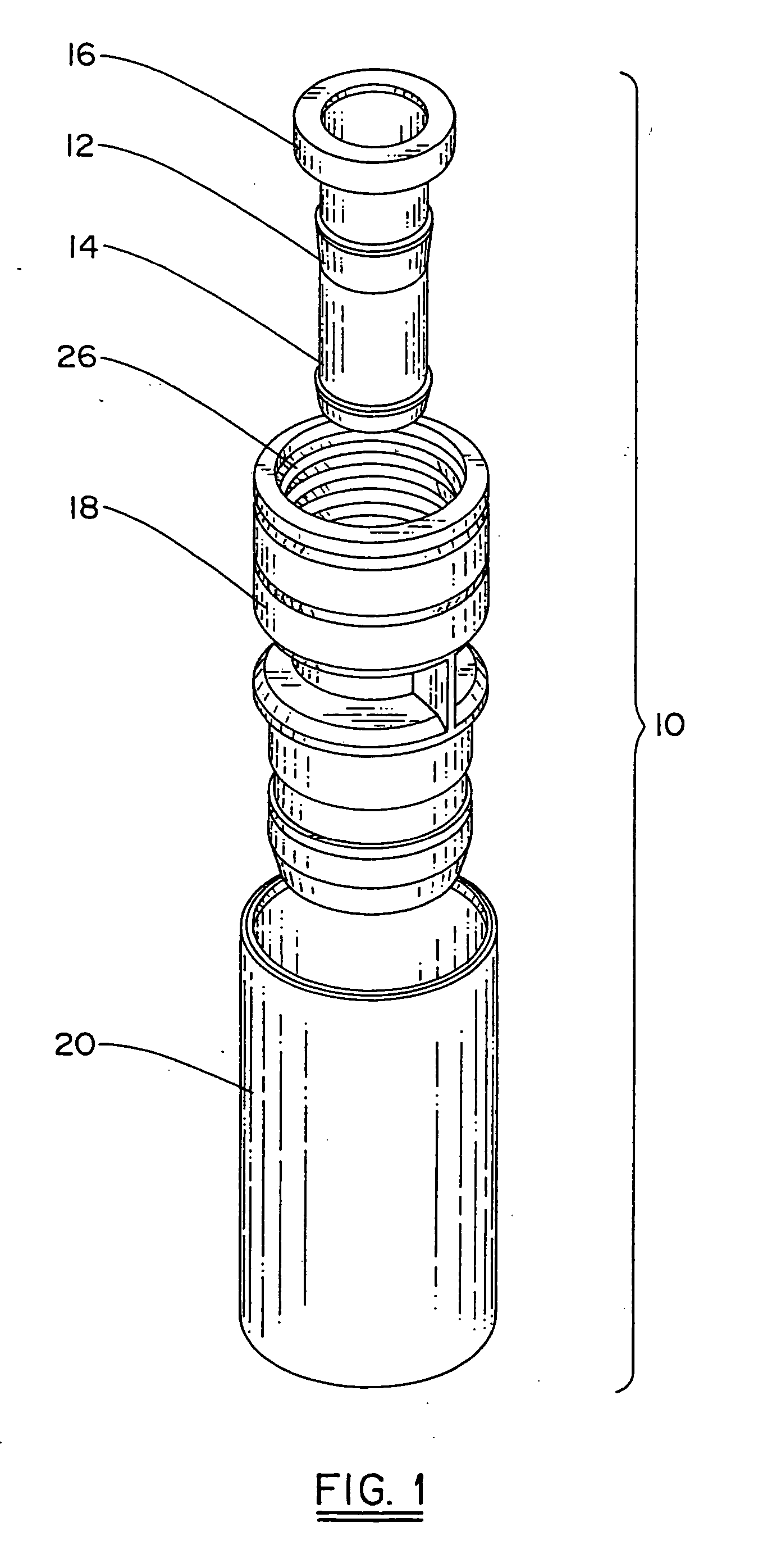
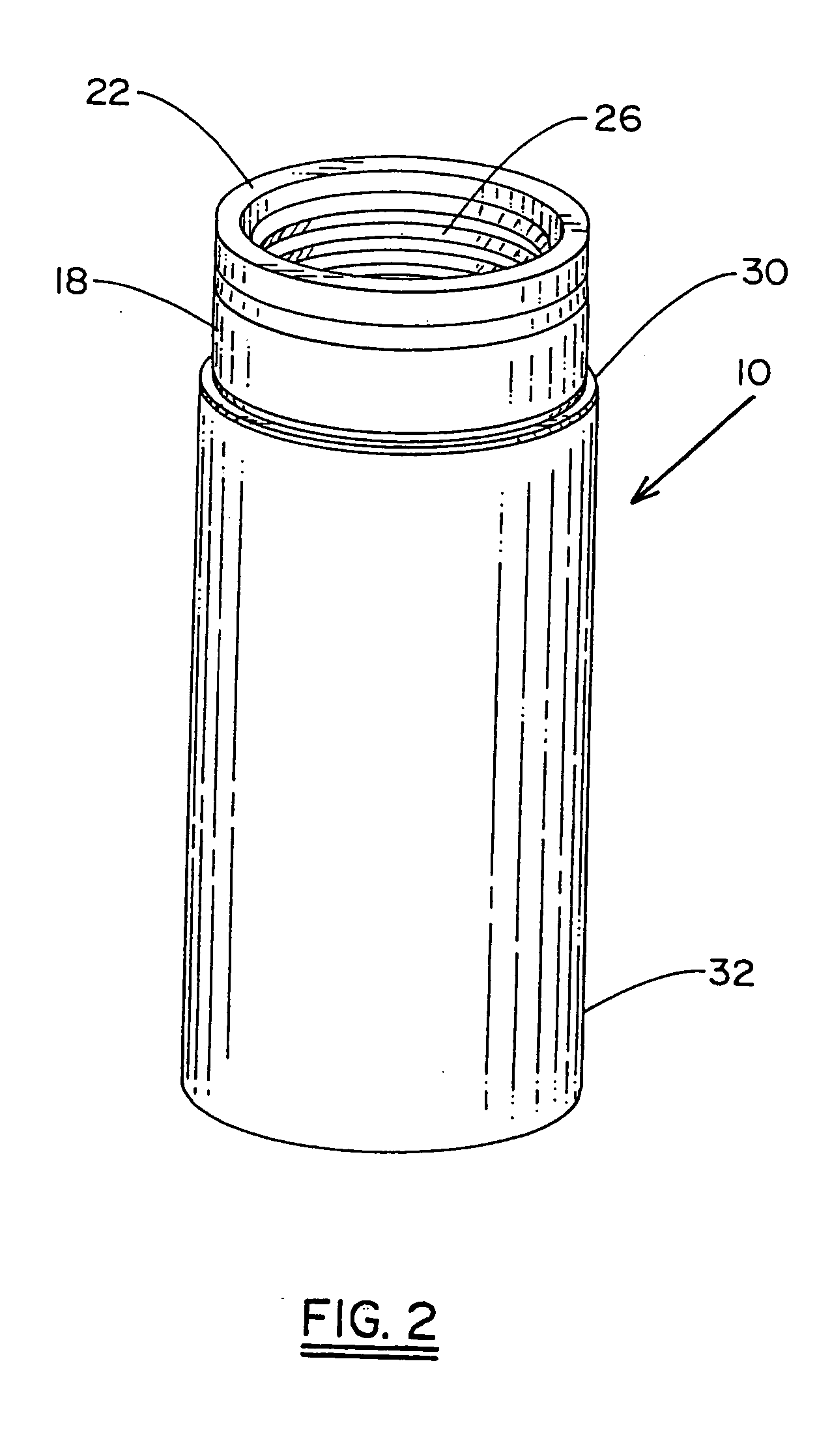
[0023] Referring now the drawings, the elements of the connector, generally denoted by reference numeral 10, are shown in FIG. 1 in exploded perspective as comprising post 12, including stem 14 and flange 16 portions, body 18 and compression ring 20. Post 12 is a metal part, substantially identical to the corresponding part of prior art connectors. Body 18 is a unitary, molded part from a suitable plastic, differing in a number of important respects from the body portions of conventional connectors, as discussed later herein in more detail. Compression ring 20 is preferably of metal and has an axial length substantially equal to that of body 18, another distinction from the usual, much shorter ring. The outer surface of ring 20 is cylindrical while the inner surface, as will be seen, is cylindrical for a portion of the ring's length and tapered for another portion. As seen in FIG. 3B, connector 10 may comprise a post 12 and ring 20 that is roll formed or drawn.

[0024] In FIGS. 2, 3...


PUM

PropertyMeasurementUnit
Forceaaaaaaaaaa
Diameteraaaaaaaaaa
Lengthaaaaaaaaaa

Abstract

In addition to the single molded part incorporating features of the conventional nut, sealing member and body, the connector includes a post and a hollow compression sealing ring. The post includes an integrally formed stem and flange portions, with the compression ring axially movable upon the body and including a tapered surface which applies a radially inward force to the body, compressing the cable and providing tight frictional engagement of the connector and cable. When in its fully installed position, the axial length of the ring is sufficient to entirely enclose the unitary body and nut, preferably having an interference fit with the outer surface of the nut portion, thus locking and sealing the connector threads to the equipment port. The compression ring is preferably of metal to shield the internal plastic parts of the connector from UV rays.

Description

FIELD OF THE INVENTION [0001] The present invention relates to connectors for coaxial cables in CATV applications and, more particularly, to a new and improved drop connector which has enhanced protection against environmental exposure and built-in tamper resistance while costing less than prior art connectors previously used in analogous applications. BACKGROUND OF THE INVENTION [0002] Threaded connectors mounted to end portions of coaxial cables are employed in the CATV industry in both indoor and outdoor applications. In either case, it is desirable to protect the end of the cable and its junction with the equipment to which it is attached from environmental hazards such as moisture and dirt. Connectors used on drop cables in outdoor installations are commonly exposed to harsher environmental conditions and, in addition, are subject to physical tampering and vandalism as, for example, in actual or attempted theft of services. As the industry moves toward “permanent” installations...

Claims


Application Information

Patent Timeline
IPC IPC(8): H01R9/05H01R13/52
CPCH01R9/0518H01R13/5205Y10T29/49123Y10T29/49174H01R2201/18
Inventor MONTENA, NOAH
Owner PPC BROADBAND INC
Learn More