Method and a machine for heat-shrinking heat-shrink sleeves engaged individually on articles such as bottles

US20050022469A1Active Publication Date: 2005-02-03SLEEVER INT

Image

  • Method and a machine for heat-shrinking heat-shrink sleeves engaged individually on articles such as bottles
  • Method and a machine for heat-shrinking heat-shrink sleeves engaged individually on articles such as bottles
  • Method and a machine for heat-shrinking heat-shrink sleeves engaged individually on articles such as bottles

Examples


Embodiment Construction

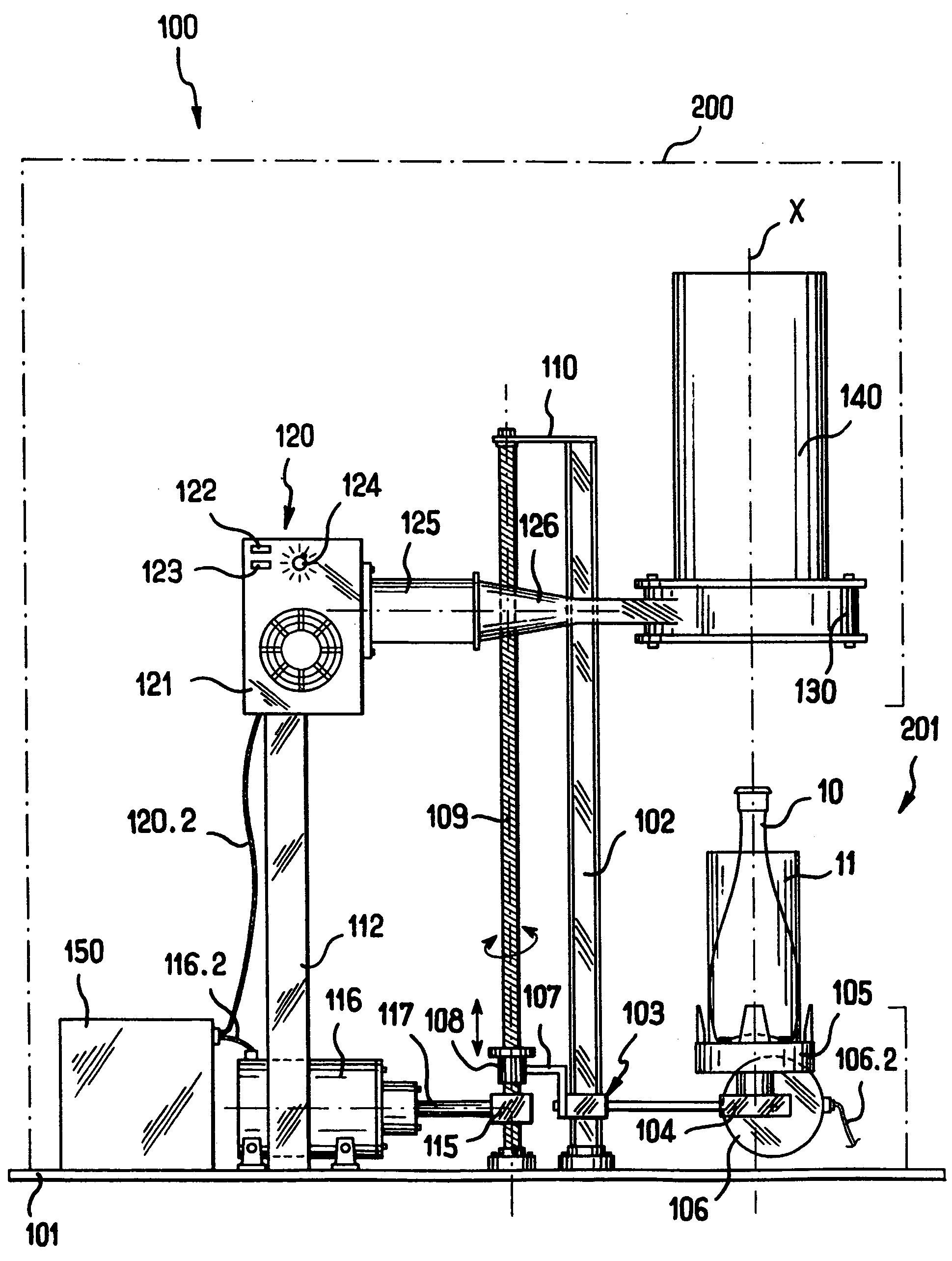
[0043] With reference to FIGS. 1 to 3, the description begins with a heat-shrink machine in accordance with the invention for implementing a method of heat-shrinking sleeves made from a film of heat-shrink plastics material and engaged individually on articles such as bottles.

[0044] Although bottles are referred to specifically herein, and do indeed represent a preferred field of application, the invention is not limited in any way to articles of this type, and can be applied equally well to other types of container or to other types of article for coating in a heat-shrink sleeve of appearance that is desired by the consumer.

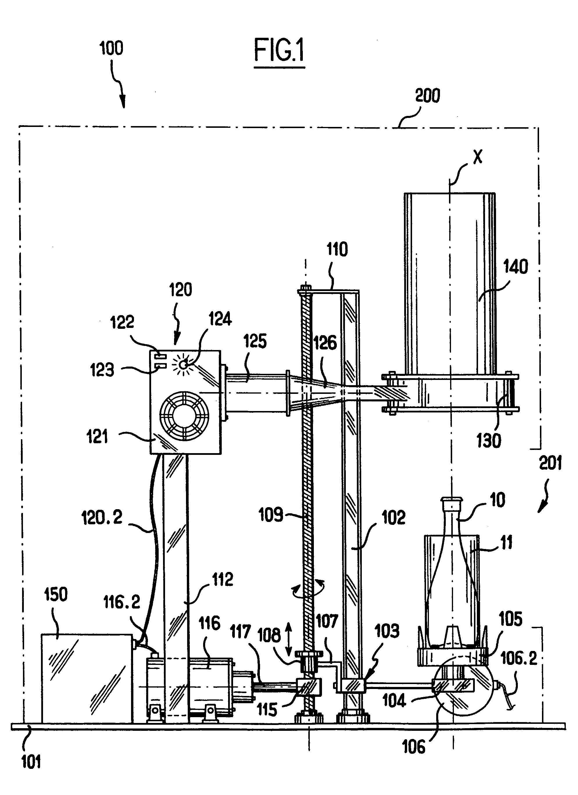
[0045] The figures show a heat-shrink machine 100 for heat-shrinking sleeves made from a film of heat-shrink plastics material that are individually engaged on articles such as bottles. The figure shows a bottle 10 having a sleeve referenced 11 associated therewith, the sleeve being put into place around said bottle.

[0046] The machine 100 comprises a stationa...


PUM

PropertyMeasurementUnit
Temperatureaaaaaaaaaa
Thicknessaaaaaaaaaa
Shrinkageaaaaaaaaaa

Abstract

The present invention relates to a method and to a machine for heat-shrinking sleeves made from a film of heat-shrink plastics material and engaged individually on articles such as bottles. In accordance with the invention, the machine comprises a fixed structure, an article support arranged to move along a vertical central axis between a low position in which articles can be put into place or removed, and a high position in which an article is fully received in a pre-heater chamber surmounting a shrinkage chamber, together with a controller governing parameters of temperature, support travel speed, and time, during the operating sequences of the method. This enables ordinary consumers themselves to cause sleeves to be shrunk onto bottles.

Description

[0001] This application is entitled to the benefit of and incorporates by reference essential subject matter disclosed in French Patent Application No. 0309426 filed on Jul. 31, 2003. FIELD OF THE INVENTION [0002] The present invention relates to the field of heat-shrinking sleeves made from a film of heat-shrink plastics material and engaged individually on articles such as bottles, for example. BACKGROUND OF THE INVENTION [0003] Continuously-operating shrinking machines have been in existence for about thirty years, and they are generally implemented in the form of a tunnel oven serving to shrink respective sleeves of heat-shrink plastics material engaged on articles which are placed on a conveyor belt forming the bottom of the shrinking tunnel. As each article travels on the conveyor belt from an upstream end towards a downstream end of the tunnel oven, the sleeve engaged on each article softens and then shrinks onto said article. [0004] Very many techniques have already been imp...

Claims


Application Information

Patent Timeline
03 Feb 2005
Publication
US20050022469A1
IPC
B65B53/02; B65B53/06
CPC
B65B53/066; B65B53/02
Inventors
FRESNEL, ERIC