Portable hand control system for a vehicle

a hand control and vehicle technology, applied in mechanical control devices, instruments, propulsion units, etc., can solve the problems of significant effort expended in developing systems, drivers with certain physical disabilities may be unable to use their legs to operate brakes and accelerator pedals, and significant percentage of driving population does not have full use of all of their limbs, etc., to achieve the effect of facilitating even pressur

Inactive Publication Date: 2005-02-03
AHNAFIELD BRUCE
View PDF11 Cites 3 Cited by
  • Summary
  • Abstract
  • Description
  • Claims
  • Application Information

AI Technical Summary

Benefits of technology

[0007] To address this continuing need, the present invention provides a system for use by a physically impaired driver for controlling the braking and acceleration functions of a vehicle. In one embodiment, the system includes a pair of control rods that can be operated by the driver to directly depress the brake and accelerator pedals of a vehicle. The control rods include telescoping shafts that can be releasably locked at a length that is comfortable for the driver. The control rods are engaged to the vehicle pedals by way of a releasable strap with an attachment eye for receiving a hook at the end of the lowermost one of the telescoping shafts. The attachment eye extends from a pressure plate that facilitates even application of pressure to the vehicle pedal. A linking member links the upper end of the two control rods to form a stable construct while allowing each control rod to be independently manipulated.

Problems solved by technology

Unfortunately, a significant percentage of the driving population does not have full use of all of their limbs.
For instance, drivers with certain physical disabilities may be unable to use their legs to operate the brake and accelerator pedals.
Although no production vehicles have been developed to account for physically-impaired drivers, a significant amount of effort has been expended in developing systems that can be integrated into an existing vehicle control system to accommodate this driving population.
Thus, this system is not available for a physically impaired driver using a vehicle other than his / her own.

Method used


Image

  • Portable hand control system for a vehicle
  • Portable hand control system for a vehicle
  • Portable hand control system for a vehicle

Examples


Embodiment Construction

[0021] For the purposes of promoting an understanding of the principles of the invention, reference will now be made to the embodiments illustrated in the drawings and described in the following written specification. It is understood that no limitation to the scope of the invention is thereby intended. It is further understood that the present invention includes any alterations and modifications to the illustrated embodiments and includes further applications of the principles of the invention as would normally occur to one skilled in the art to which this invention pertains.

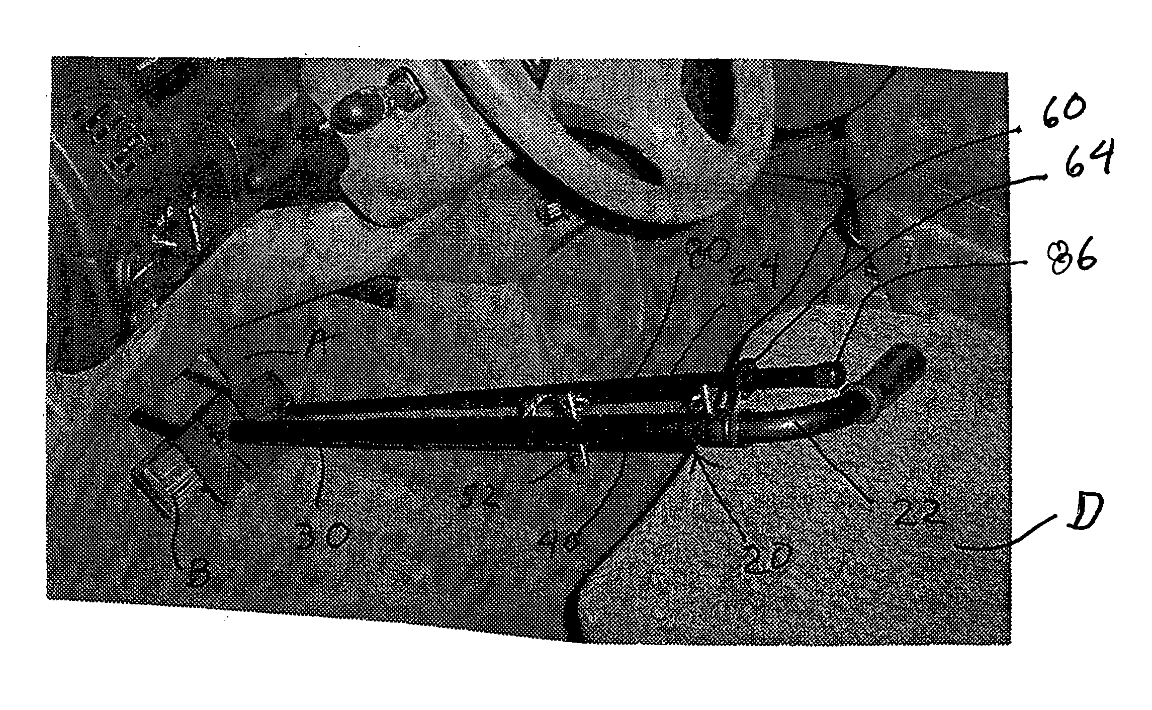
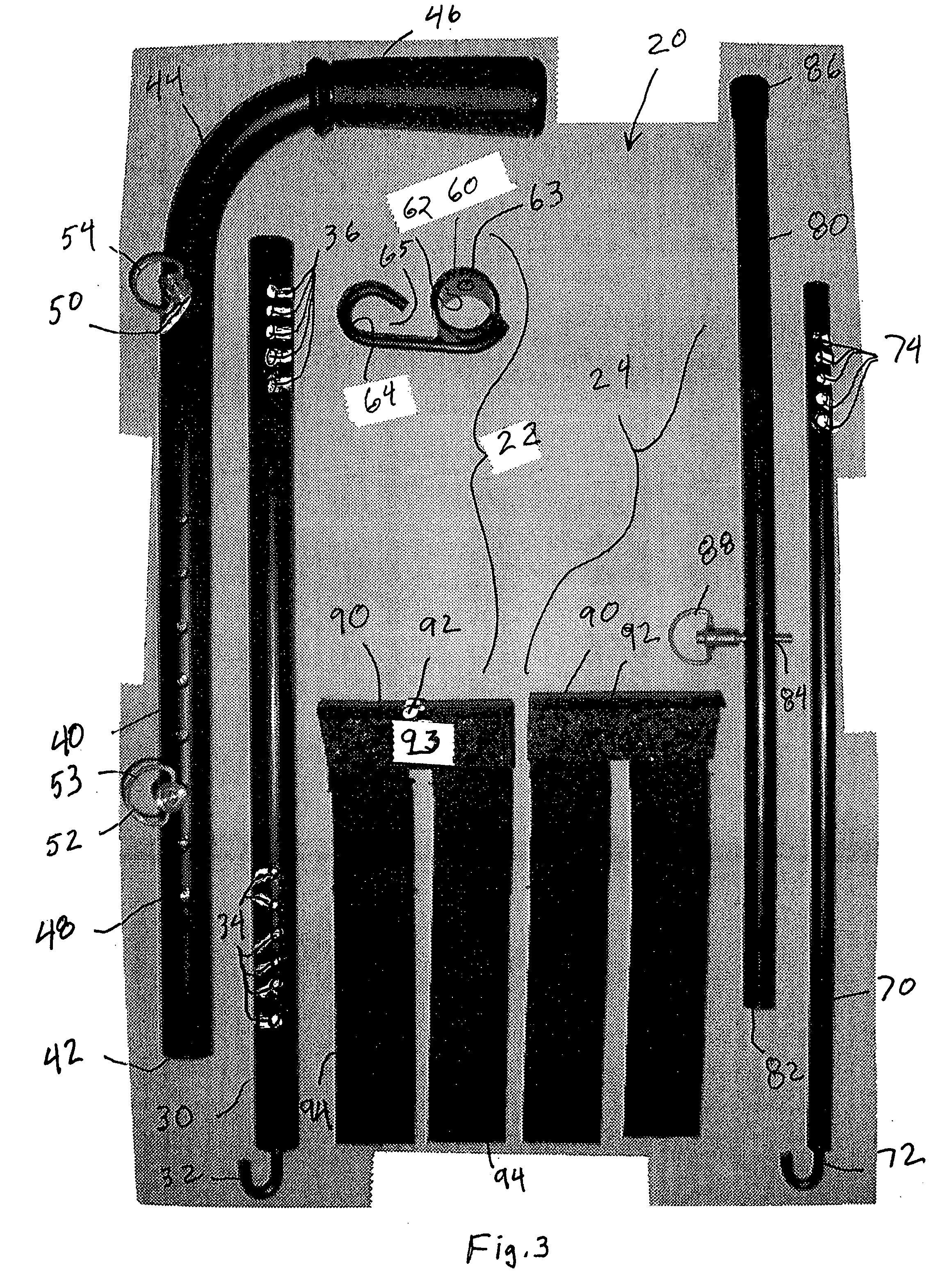
[0022] The present invention contemplates a portable hand control system 20, as shown in FIG. 2, which allows a physically challenged driver to use virtually any vehicle. Specifically, the system provides a direct interface with the existing vehicle brake and accelerator pedals. The system 20 includes a pair of control rod assemblies 22 and 24, with the first control rod assembly 22 providing an interface to t...


PUM


Abstract

A portable vehicle control system for use by physically challenged drivers includes a pair of control rods that can be operated by the driver to directly depress the brake and accelerator pedals of a vehicle. The control rods include telescoping shafts that can be releasably locked at a length that is comfortable for the driver. The control rods are engaged to the vehicle pedals by way of a releasable strap with an attachment eye for receiving a hook at the end of the lowermost one of the telescoping shafts. The attachment eye extends from a pressure plate that facilitates even application of pressure to the vehicle pedal. A linking member links the upper end of the two control rods to form a stable construct while allowing each control rod to be independently manipulated.

Description

CROSS-REFERENCE TO RELATED APPLICATION [0001] This application claims priority to co-pending provisional application No. 60 / 491,798, filed on Aug. 1, 2003, the disclosure of which is incorporated herein by reference.BACKGROUND OF THE INVENTION [0002] The present invention relates to a system for controlling a motor vehicle, and particularly for operating the vehicle accelerator and brakes. This invention can be readily applied to vehicle control systems for physically impaired drivers. [0003] A conventional motor vehicle, such as an automobile, is designed for a driver having full and substantially unrestricted use of all of their limbs. The standard vehicle controls include a rotary operating steering wheel, a depressible brake pedal, and a depressible accelerator pedal. Of course, it is known that the steering wheel is operated manually, while the brake and accelerator pedals are operated by the driver's feet. Current production vehicles assume that the driver has full use of his / ...

Claims


Application Information

Patent Timeline
Patent Type & Authority Applications(United States)
IPC IPC(8): B60K23/00B60K26/00B60K26/02G05G1/54
CPCB60K2741/003G05G1/54B60W30/18B60W10/04B60W10/18B60W2710/0605B60W2710/18
Inventor AHNAFIELD, BRUCE
Owner AHNAFIELD BRUCE
Why Eureka
Try Eureka