Conveyor belt scraper

a conveyor belt and belt technology, applied in the direction of conveyor parts, cleaning, transportation and packaging, etc., can solve the problem of further stress on the biasing member in the first direction

Inactive Publication Date: 2005-02-03
SLIC TRADING
View PDF6 Cites 8 Cited by
  • Summary
  • Abstract
  • Description
  • Claims
  • Application Information

AI Technical Summary

Benefits of technology

[0023] In one form of the invention the scraper element includes first and second deflector plates and the scraping edge component is secured to respective first ends of the plates. The biasing member is positioned between the plates and preferably is secured to one of the plates. One of the plates may abut the support, or any other structure, thereby to retain the biasing member in a prestressed condition. The extent to which the biasing member may be prestressed may be limited when the other plate is brought into contact with the support or other structure or adjustable stops for, in this way, movement of the biasing member may be controlled.

Problems solved by technology

Movement of the scraping edge away from the belt surface, which occurs during use, leads to the biasing member being further stressed in the first direction.

Method used


Image

  • Conveyor belt scraper
  • Conveyor belt scraper

Examples


Embodiment Construction

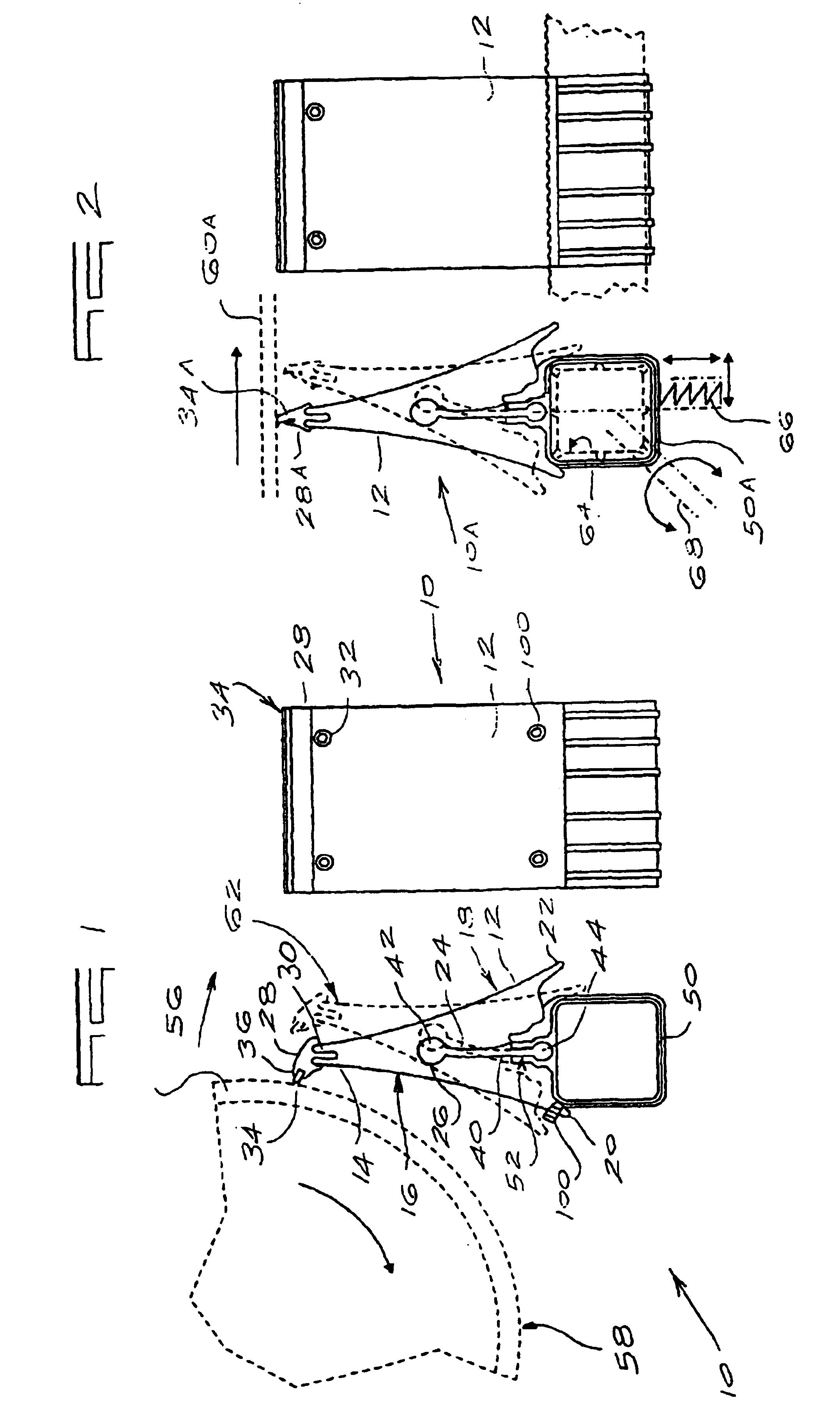
[0034]FIG. 1 of the accompanying drawings illustrates a conveyor scraper element 10 according to a first form of the invention from a side and from one end respectively. In this example the conveyor scraper element includes a body 12 which is moulded from a suitable plastics material, eg. reinforced nylon, and which has a roughly triangular shape in cross section. An upper end or apex of the body has an elongate groove 14 which is narrower at its mouth than at its base. Sides 16 and 18 of the body taper outwardly and downwardly from the apex and are referred to herein as deflector surfaces.

[0035] At its lower end the body has two wings or ribs 20 and 22 respectively projecting downwardly from the deflecting sides 16 and 18.

[0036] A central portion of the body is formed with a fairly substantial slot 24 which has a base 26 which is in the nature of a circular cylinder.

[0037] A scraping component 28 is mounted to the slot 14. The component 28 has a rib 30 which is of complementary ...


PUM


Abstract

A method of assembling a conveyor belt scraper which includes at least one scraping edge fixed to a support at least by means of a biasing member which includes the steps of prestressing the biasing member in a first sense, maintaining the biasing member prestressed, and mounting the conveyor belt scraper adjacent a surface of the belt whereby, in use, when the scraping edge exerts a scraping action on the belt and is deflected away from the belt, the biasing member is further stressed in the first sense.

Description

BACKGROUND OF THE INVENTION [0001] This invention relates generally to a conveyor belt scraper. [0002] It is known to make use of a conveyor scraper wherein the scraping element, or each scraping element when there are a plurality of such elements, is flexible or is mounted to a spring of suitable form which allows to-and-fro movement of the scraping element, during use. [0003] With the aforementioned type of scraper cleaning of a conveyor belt is achieved by adjusting each scraping element towards the belt surface and applying pressure so that the flexible scraping element, or the spring, as the case may be, is tensioned to remove slack and creep and to provide the necessary resistance to the moving belt so that material adhering to the belt is removed. [0004] The pressure which is applied to flex the scraping element or tension the spring is obtained by forcing an edge of the scraping element into contact with the belt surface, with a suitable degree of force. The pressurised cont...

Claims


Application Information

Patent Timeline
Patent Type & Authority Applications(United States)
IPC IPC(8): B65GB65G45/16
CPCB65G45/16
Inventor BRINK, JAN LOUIS
Owner SLIC TRADING
Why Eureka
Try Eureka